
Baseline wander correction for communication receivers

a correction and communication receiver technology, applied in the field of data communication, can solve the problems of erroneous sampled values of affected pulses, substantial interference source of echo baseline wander, and unsuitability for higher data ra

Active Publication Date: 2008-07-03
TEXAS INSTR INC
View PDF7 Cites 36 Cited by
  • Summary
  • Abstract
  • Description
  • Claims
  • Application Information

AI Technical Summary

Benefits of technology

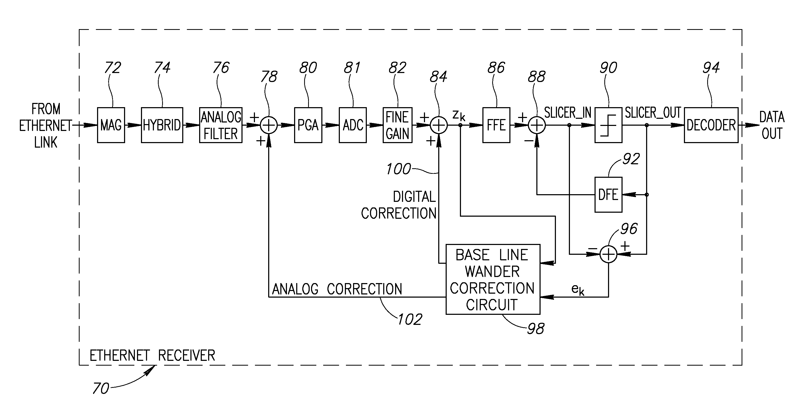
[0019]The mechanism of the present invention overcomes the problems associated with the prior art by providing a solution based on a parametric model of the high pass filters causing the baseline wander. This results in an accurate correction signal that is subsequently partitioned into separate analog and digital correction signals. Use of the mechanism of the present invention provides more accurate baseline wander mitigation and improved receiver performance over than prior art solutions.

Problems solved by technology

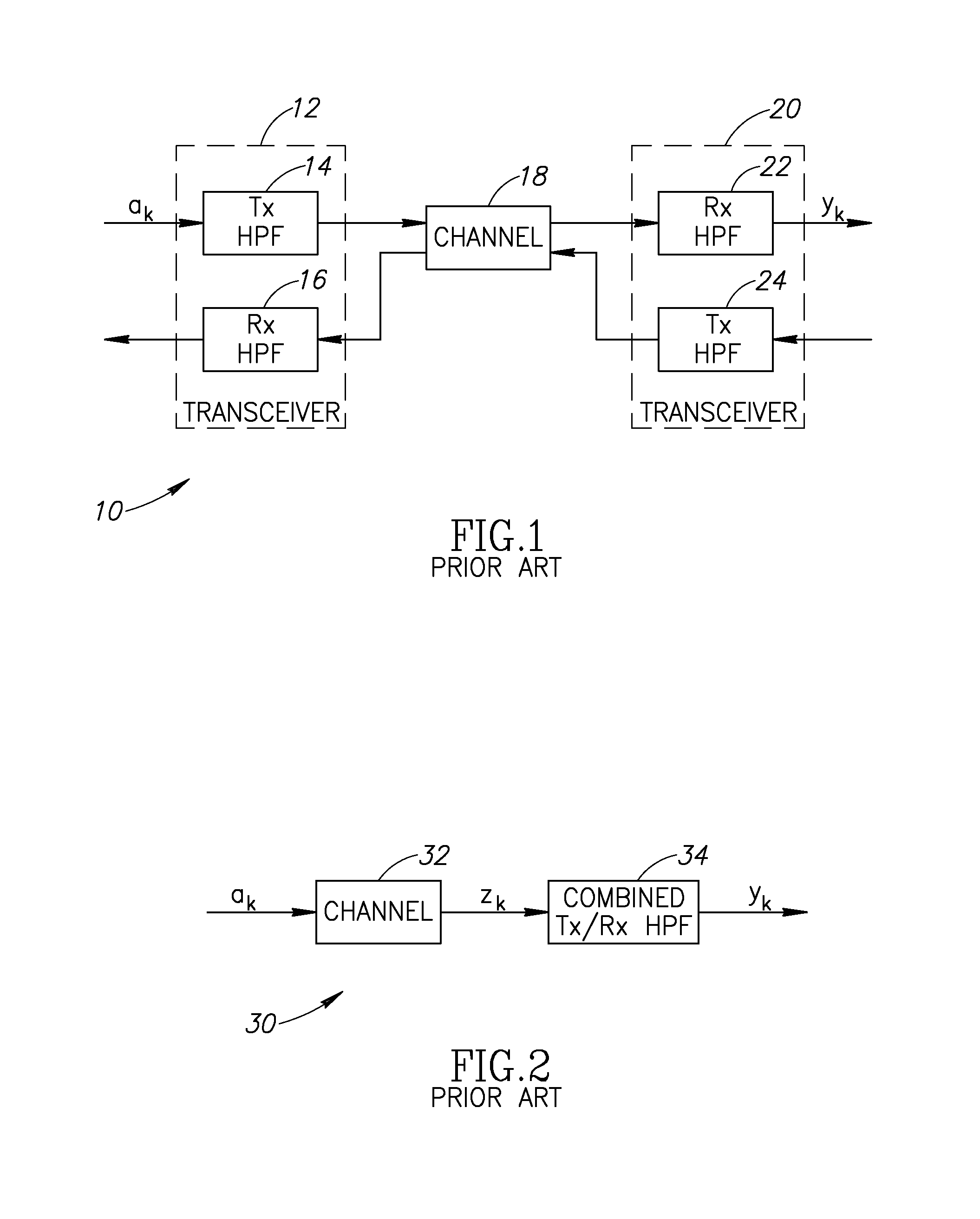
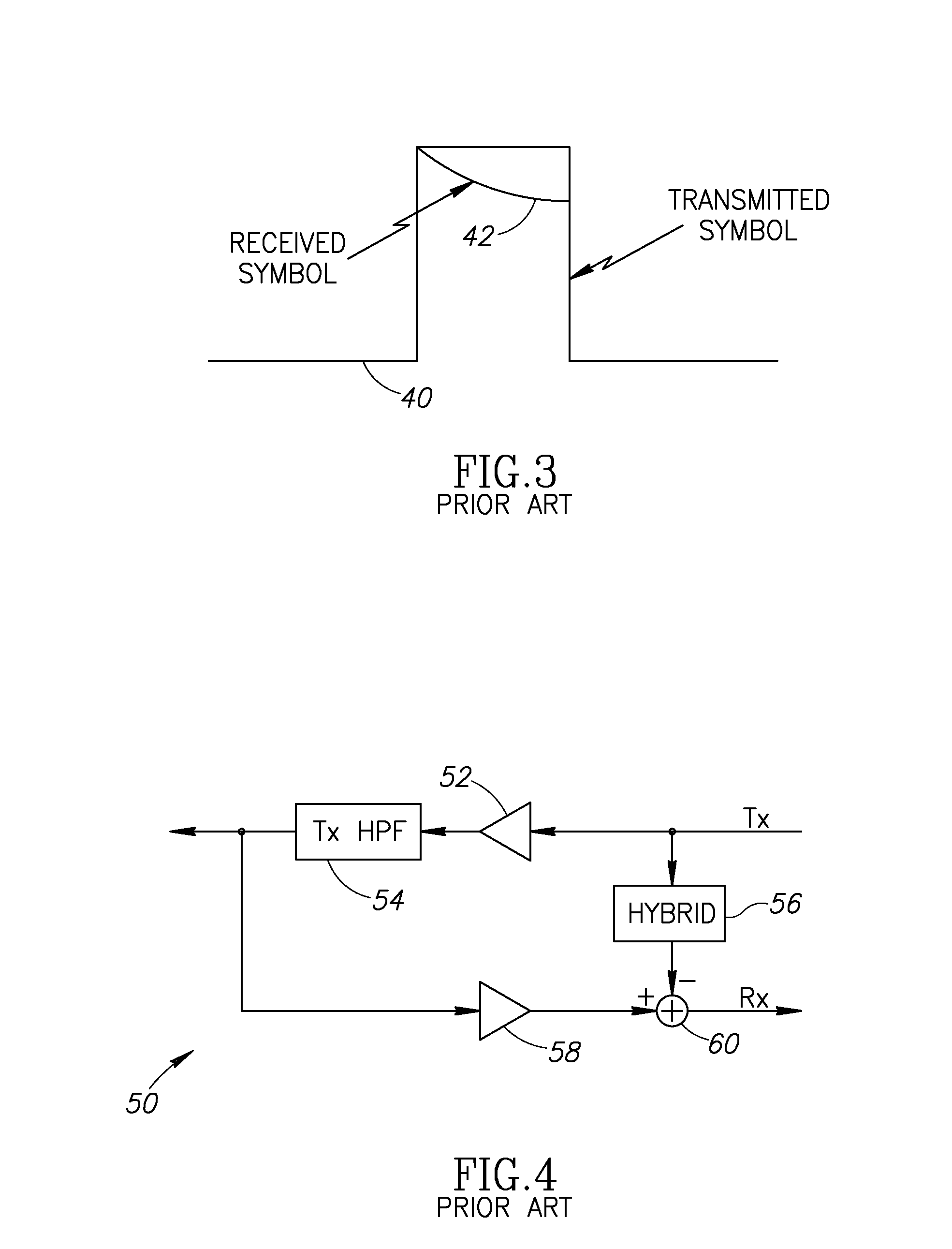
It is noted that in long strings of identical symbols, the droop can become so severe that the voltage level passes through the decision threshold, resulting in erroneous sampled values for the affected pulses.
In fact, it can be up to 10 dB stronger then the far end signal, which makes the echo baseline wander a substantial source of interference.
While certain data patterns can cause very severe baseline wander, statistically random data can reduce the amount of baseline wander, but it would still be significant.
A problem with Manchester encoding, however, it that it introduces frequency related problems that make it unsuitable for use at higher data rates.
Further, even if a killer packet enters the scrambler, a problem arises only if the data pattern aligns with the scrambler seed.
Ethernet protocol limits error handling to detection of bit errors in the received frame.

Method used


Image

  • Baseline wander correction for communication receivers
  • Baseline wander correction for communication receivers
  • Baseline wander correction for communication receivers

Examples


Embodiment Construction

Notation Used Throughout

[0039]The following notation is used throughout this document.

TermDefinitionACAlternating CurrentADCAnalog to Digital ConverterASICApplication Specific Integrated CircuitBLWBaseline WanderDCDirect CurrentDFEDecision Feedback EqualizerDSPDigital Signal ProcessorFEXTFar-End CrosstalkFFEFeed Forward EqualizerFPGAField Programmable Gate ArrayGEGigabit EthernetHDLHardware Description LanguageHPFHigh Pass FilterICIntegrated CircuitIEEEInstitute of Electrical and Electronics EngineersISIIntersymbol InterferenceLMSLeast Mean SquaresLPFLow Pass FilterNEXTNear-End CrosstalkPAMPulse Amplitude ModulationRFRadio FrequencySTPShielded Twisted PairUTPUnshielded Twisted Pair

DETAILED DESCRIPTION OF THE INVENTION

[0040]The present invention is a novel and useful apparatus for and method of baseline wander cancellation for use in transformer coupled, baseband communication receivers. The mechanism of the present invention is applicable to many types of wired networks and is parti...


PUM


Abstract

A novel and useful baseline wander correction mechanism for use with transformer coupled baseband communication receivers. Parametric estimation of the transformer model is used estimate and cancel the baseline wander effect. A parametric model is used to model the baseline wander impairment created by the transmitter and receiver transformers as a high pass filter having an exponential decay parameter alpha. A correction signal for both the far end and echo signal paths are calculated and summed to generate a total correction signal. The total correction signal is partitioned into an analog correction signal that is applied to the analog portion of the communications receiver and into a digital correction signal that is similarly applied to the analog portion of the communications receiver.

Description

FIELD OF THE INVENTION[0001]The present invention relates to the field of data communications and more particularly relates to an apparatus for and method of baseline wander correction for use in communication receivers.BACKGROUND OF THE INVENTION[0002]Modern network communication systems are generally of either the wired or wireless type. Wireless networks enable communications between two or more nodes using any number of different techniques. Wireless networks rely on different technologies to transport information from one place to another. Several examples, include, for example, networks based on radio frequency (RF), infrared, optical, etc. Wired networks may be constructed using any of several existing technologies, including metallic twisted pair, coaxial, optical fiber, etc.[0003]Communications in a wired network typically occurs between two communication transceivers over a length of cable making up the communications channel. Each communications transceiver comprises a tr...

Claims


Application Information

Patent Timeline
IPC IPC(8): H04B3/04
CPCH04L25/063H04L25/0266
Inventor MILLER, MORYAGIL, ARIELLUSKY, ITAYBRECHER, LIRANPELEG, AMIRSOMMER, NAFTALI
Owner TEXAS INSTR INC
Learn More