Radiation imaging apparatus, method of controlling the radiation imaging apparatus and computer-readable storage medium

a radiation imaging apparatus and radiation imaging technology, applied in electrical devices, medical science, diagnostics, etc., can solve the problems of skin or health hazards, difficult to suppress exposure hazards, difficult to use x-ray imaging apparatuses, etc., and achieve the effect of preventing excessive emission of x-rays

Inactive Publication Date: 2008-07-03
CANON KK
View PDF2 Cites 9 Cited by
  • Summary
  • Abstract
  • Description
  • Claims
  • Application Information

AI Technical Summary

Benefits of technology

[0018]According to the present invention, it is possible to prevent excessive emission of X-rays in manually setting an X-ray intensity and allow an operator to set a proper X-ray intensity.

Problems solved by technology

Exposure to X-rays during surgery may cause skin or health hazards such as temporary alopecia.
It is therefore difficult for an X-ray imaging apparatus to determine an X-ray intensity by automatic control only, and hence it is necessary to carry out adjustment of an X-ray intensity manually.
The first problem is that the conventional scheme of generating a warning on the basis of only exposure time regardless of the intensity of X-rays applied has difficulty in suppressing exposure hazards because the warning generated in this manner is irrelevant to the exposure dose.
The second problem is that the scheme of selecting a preset X-ray intensity in accordance with, for example, the selection of an imaging region has a risk of causing excessive emission of X-rays when an operator performs readjustment after selection.
In this case, it is difficult to suppress excessive emission of X-rays.
Even automatic control needs to accept adjustment by the operator, and hence has a similar problem.

Method used


Image

  • Radiation imaging apparatus, method of controlling the radiation imaging apparatus and computer-readable storage medium
  • Radiation imaging apparatus, method of controlling the radiation imaging apparatus and computer-readable storage medium
  • Radiation imaging apparatus, method of controlling the radiation imaging apparatus and computer-readable storage medium

Examples


first embodiment

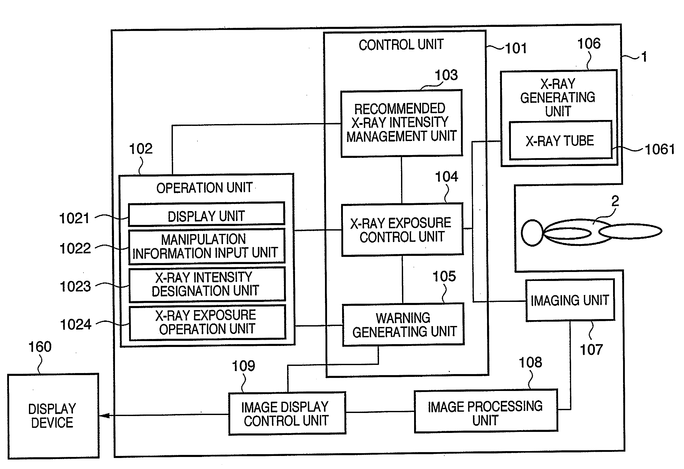
[0029]FIG. 1 is a block diagram showing the arrangement of an X-ray imaging apparatus 1 according to the first embodiment. In the X-ray imaging apparatus1, a control unit 101 performs overall control of the X-ray imaging apparatus 1. The control unit 101 includes a CPU and a storage unit (computer-readable memories such as a ROM, RAM, and hard disk) as constituent elements. The CPU controls operation of each constituent element of the X-ray imaging apparatus 1. Of the storage units, the ROM and the hard disk can store programs necessary for the operation and control of the X-ray imaging apparatus 1, parameters necessary for X-ray exposure, information associated with a subject 2 as a target, and the like. The RAM can be used as a work area for the CPU.

[0030]An operation unit 102 which accepts operation by an operator includes a display unit 1021 which displays operation contents and a manipulation information input unit 1022 for inputting manipulation information. The operation unit...

second embodiment

[0058]FIG. 4 is a block diagram showing the arrangement of an X-ray imaging apparatus 41 according to the second embodiment. The same reference numerals of the constituent elements of the X-ray imaging apparatus 1 according to the first embodiment denote the same constituent elements in the second embodiment, and a repetitive description will be omitted.

[0059]A communication unit 401 is a circuit which comprises an X-ray information reception unit 4011 which can be connected to a network 150, and can communicate with an external apparatus such as an external information management apparatus or another image diagnostic apparatus through the X-ray information reception unit 4011. The X-ray information reception unit 4011 can hold a recommended X-ray intensity, patient information, manipulation information, and the like transmitted from an external apparatus such as an information management apparatus. It is possible to obtain a proper recommended X-ray intensity from an external infor...

third embodiment

[0124]The first embodiment has exemplified the arrangement of the operation unit 102, in which the adjustment knob comprising the rotary encoder and the servo motor is used as the X-ray intensity designation unit. However, the operation unit 102 may have another arrangement. For example, the operation unit 102 may comprise a touch panel and membrane switches.

[0125]FIG. 7 is a view showing an example of the arrangement of an operation unit 702 using a touch panel. The operation unit 702 comprises a display unit 1021 and a manipulation information input unit 7022 comprising a touch panel and membrane switches. On an X-ray intensity designation unit 7023, an X-ray intensity increase button 7024 and an X-ray intensity decrease button 7025 are arranged. Pressing the X-ray intensity increase button 7024 or the X-ray intensity decrease button 7025 makes it possible to increase or decrease the emitted X-ray intensity. For example, this operation unit may be configured such that when a speci...


PUM


Abstract

An X-ray imaging apparatus includes an X-ray intensity designation unit which designates an emitted X-ray intensity of X-rays applied to a target, an X-ray exposure control unit which compares a predetermined recommended X-ray intensity with the emitted X-ray intensity designated by the X-ray intensity designation unit to determine whether the emitted X-ray intensity becomes equal to or more than the recommended X-ray intensity, and a warning generating unit which generates a warning signal indicating that the emitted X-ray intensity becomes equal to or more than the recommended X-ray intensity, on the basis of the determination made by the X-ray exposure control unit.

Description

BACKGROUND OF THE INVENTION[0001]1. Field of the Invention[0002]The present invention relates to a radiation imaging technique which prevents an excessive increase in the exposure amount of a patient.[0003]2. Description of the Related Art[0004]X-ray image diagnosis using X-rays has become indispensable to modern medical services. X-ray image diagnosis has also been generally used for X-ray interpretation using still images. Currently, however, the application of X-ray image diagnosis has extended to examination and surgery support using X-ray fluoroscopy.[0005]In particular, interventional radiology (IVR) has been executed, which allows a doctor to perform treatment by using a catheter inserted in a blood vessel while fluoroscoping the inside of a patient (subject) using X-rays. Executing interventional radiology (IVR) makes it possible to perform surgery on a portion which has been in the past difficult to perform a surgical operation, e.g., the heart or brain.[0006]X-rays can be ...

Claims


Application Information

Patent Timeline
Patent Type & Authority Applications(United States)
IPC IPC(8): H05G1/10
CPCA61B6/542A61B6/00
Inventor YOSHIDA, TAKASHI
Owner CANON KK
Why Eureka
Try Eureka