Varnish coating device and method for coating a varnish
- Summary
- Abstract
- Description
- Claims
- Application Information
AI Technical Summary
Benefits of technology
Problems solved by technology
Method used
Image

Examples
first preferred embodiment
[0052](Structure of a Varnish Coating System)
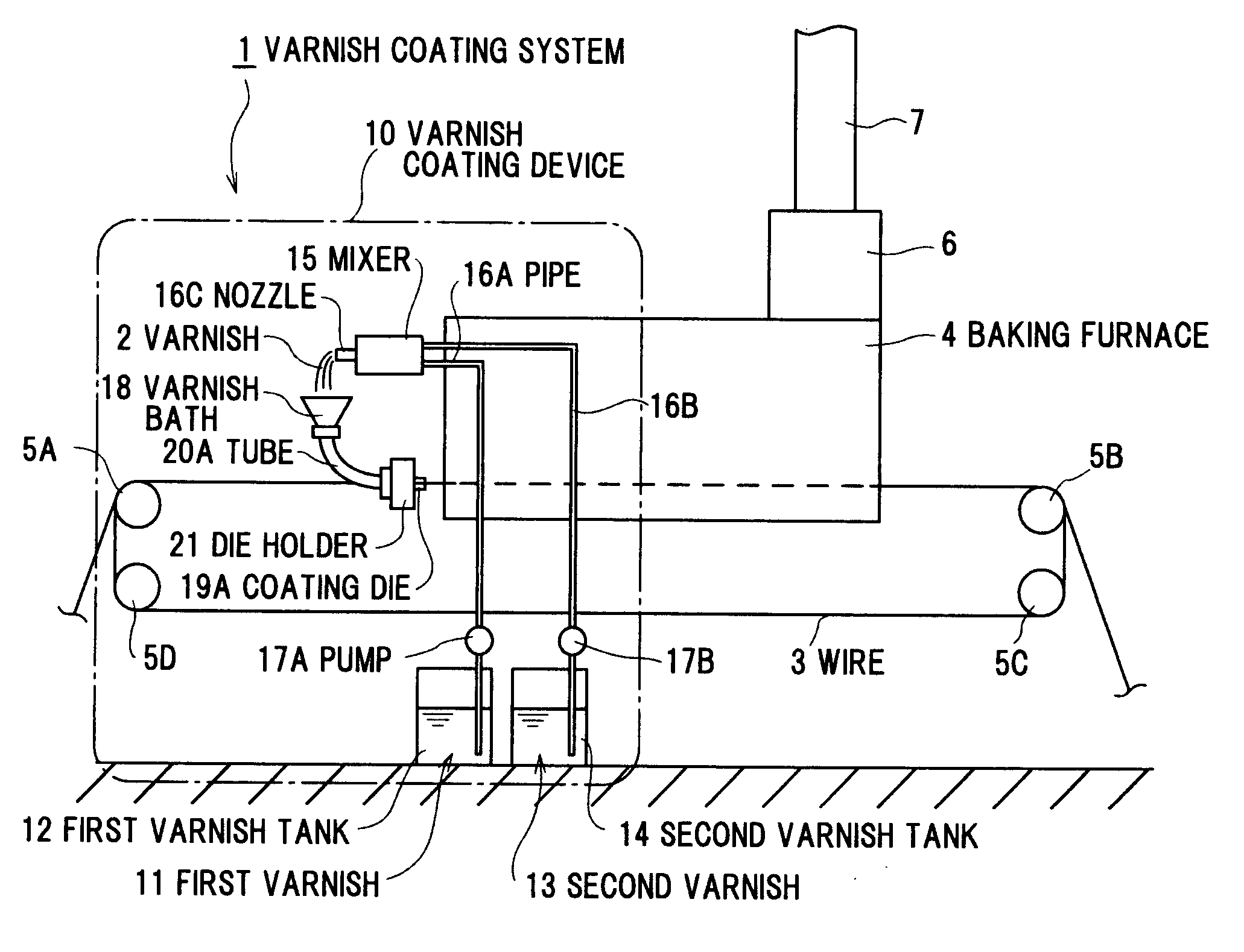
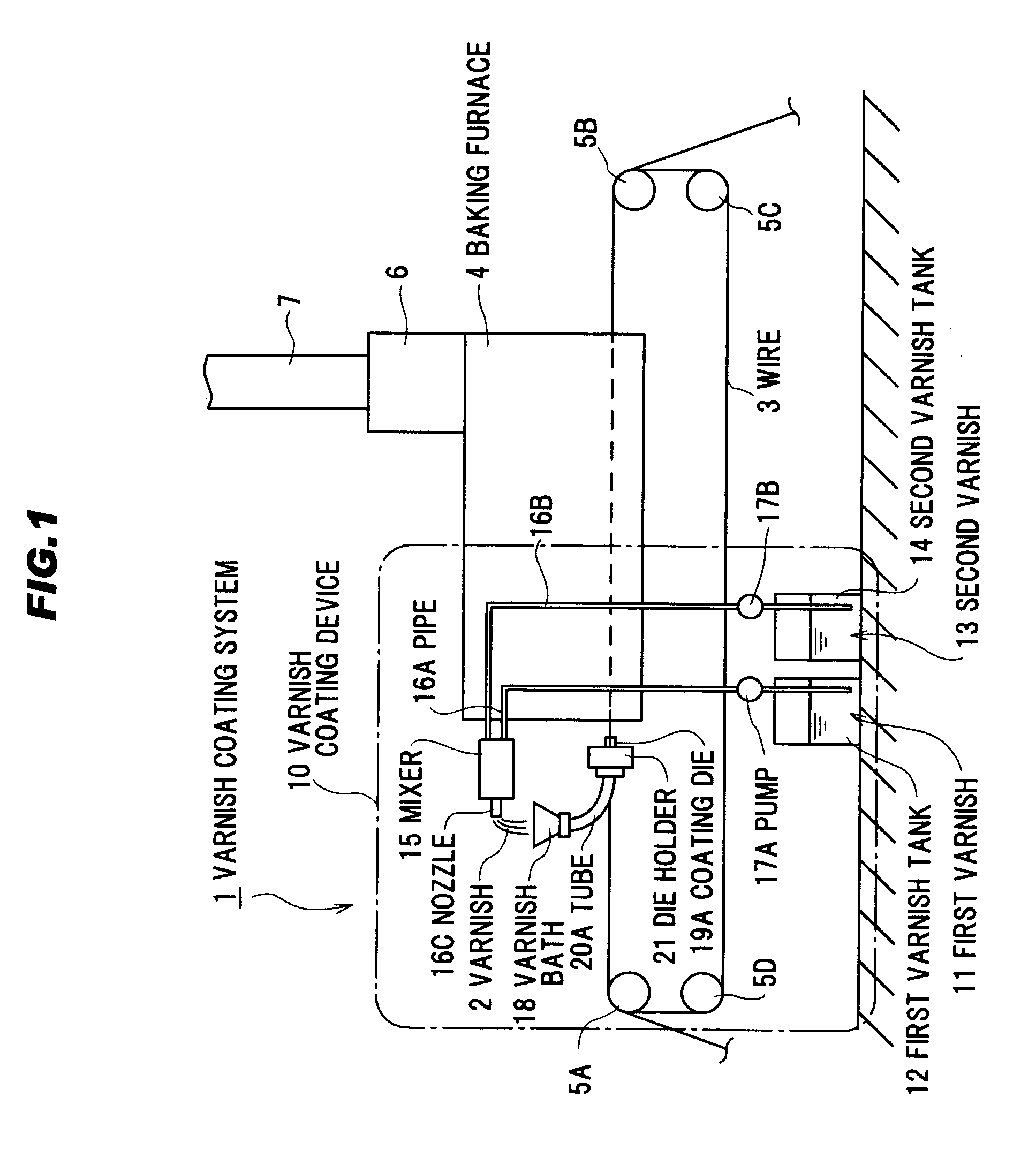
[0053]FIG. 1 is a schematic diagram of a varnish coating system in a first preferred embodiment according to the present invention.
[0054]A varnish coating system 1 comprises a varnish coating device 10 for applying a varnish 2 made by mixing two different liquids to a wire 3, a baking furnace 4 for drying the varnish 2 applied to the wire 3, sheaves (or rollers) 5A to 5D having grooves at an outer periphery of the sheaves 5A to 5D for carrying the wire 3 such that the wire 3 can pass through the varnish coating device 10 and the baking furnace 4 for a plural times (herein, six times), a catalytic device 6 installed on the baking furnace 4, and an exhaust duct 7 installed on an exhaust port of the catalytic device 6.
[0055]In addition, a winder (not shown) or the like is installed at a later stage of the baking furnace 4 with respect to the wire 3, and illustration of these parts is omitted from FIG. 1. Similarly, a bare wire pay-off (not s...
second preferred embodiment
[0081]FIG. 5 is a schematic diagram of a varnish coating device in a second preferred embodiment according to the present invention.
[0082]A varnish coating device 10 in the second preferred embodiment is similar to the varnish coating device 10 in the first preferred embodiment, except that a varnish bath 30 having an L-shape is directly connected to the coating dies in place of providing the tubes 20A-20F in the first preferred embodiment. In the following explanation, same reference numerals indicate parts having similar structure and function. In this preferred embodiment, the varnish bath 30 having the L-shape is used, however, the present invention is not limited thereto. Similar effect can be obtained by providing the varnish bath having a configuration for supplying the varnish 2 to the coating dies 19A-19F without stagnation of the varnish 2.
[0083]FIG. 6 is a plan view of the varnish bath of FIG. 5. FIG. 7 is a side view of the varnish bath of FIG. 6 viewed from a wire intro...
third preferred embodiment
[0090]FIG. 8 is a plan view of a main part of the varnish coating device in a third preferred embodiment according to the present invention. FIG. 9 is a cross sectional view of the varnish coating device shown in FIG. 8. In FIG. 8, a part of the tube is shown along broken line.
[0091]A varnish coating device 10 in the third preferred embodiment is similar to the varnish coating device 10 in the second preferred embodiment, except that the varnish bath 30 and the coating dies 19A-19F are provided separately and connected with each other by the tubes 20A-20F, and the front wall 31 and the partition 35 of the varnish bath 30 are inclined. In addition, since a method for installing the wire 3 and a method for applying the varnish 2 in the varnish coating device 10 to the wire 3 are similar to those in the second preferred embodiment, therefore, the explanation thereof is omitted.
[0092]According to the third preferred embodiment, it is possible to reduce the stagnation of the varnish 2 to...
PUM
 Abstract
Description
Claims
Application Information
 - R&D Engineer
- R&D Manager
- IP Professional
- Industry Leading Data Capabilities
- Powerful AI technology
- Patent DNA Extraction
Browse by: Latest US Patents, China's latest patents, Technical Efficacy Thesaurus, Application Domain, Technology Topic.
© 2024 PatSnap. All rights reserved.Legal|Privacy policy|Modern Slavery Act Transparency Statement|Sitemap