

Methods and apparatus for fabricating a rotor assembly
a technology of rotor blades and rotors, which is applied in the direction of blade accessories, machines/engines, waterborne vessels, etc., can solve the problems of high airfoil stress and the effect of tip rubs being more severe to the airfoil, and achieve the effect of facilitating radial loading and reducing radial load
- Summary
- Abstract
- Description
- Claims
- Application Information
AI Technical Summary
Benefits of technology
Problems solved by technology
Method used
Image

Examples
Embodiment Construction
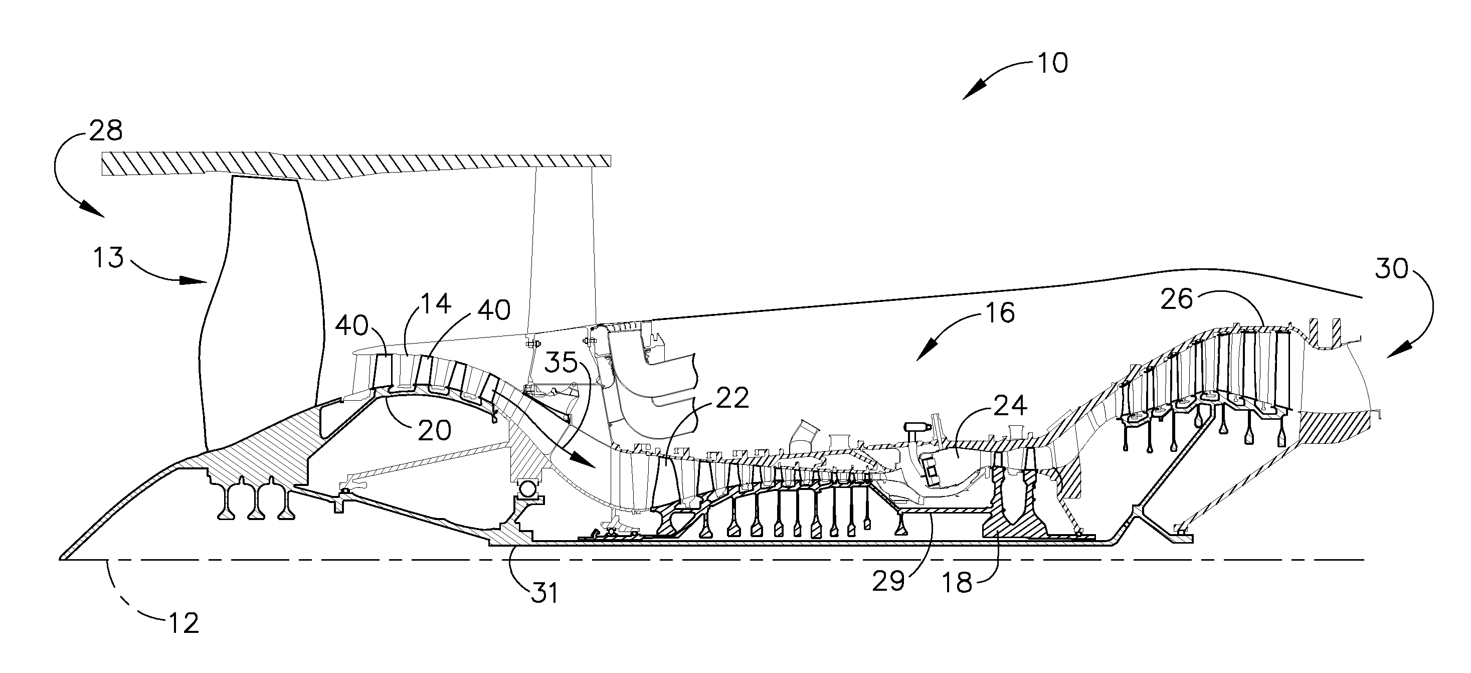
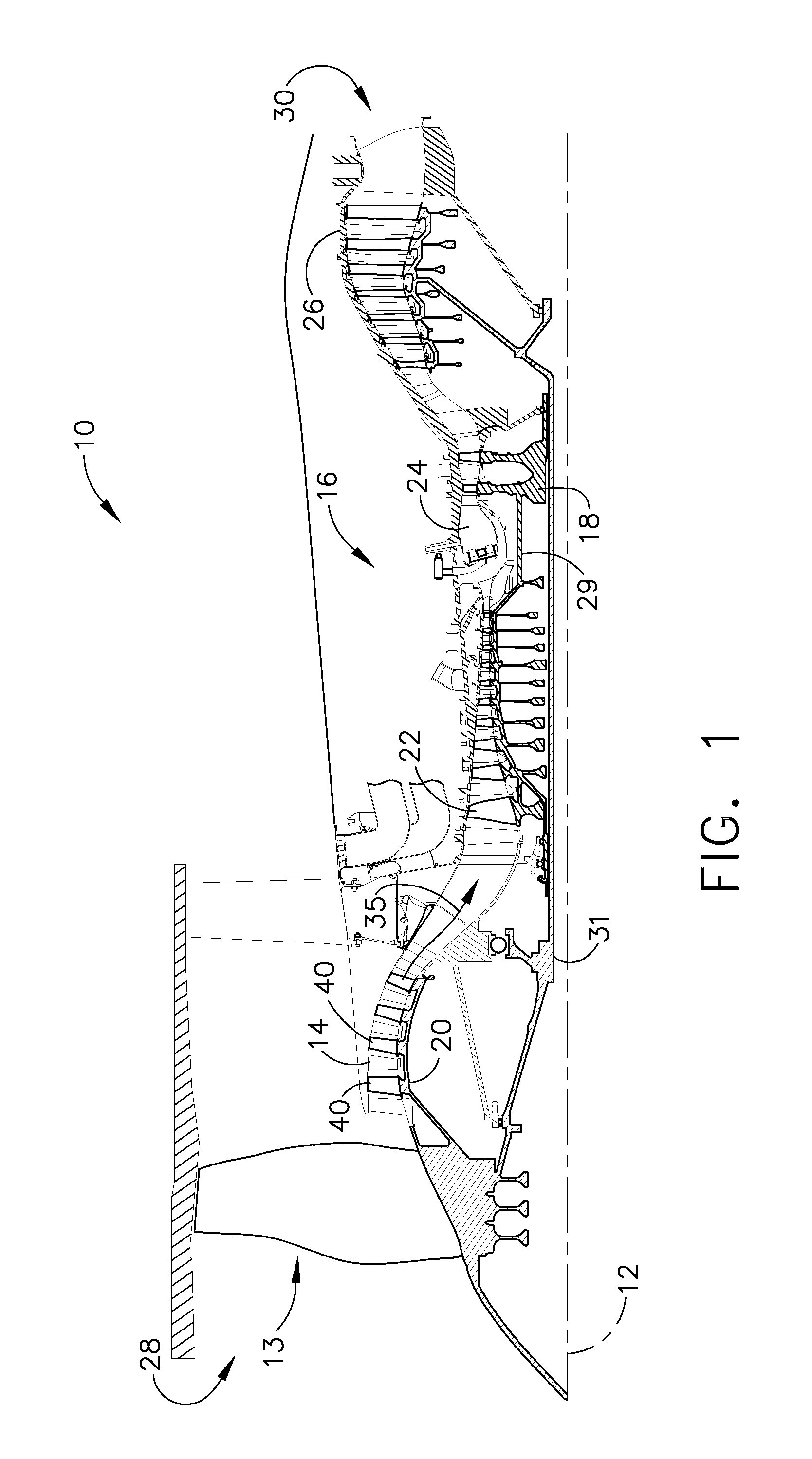
[0012]The present invention provides an exemplary apparatus and method for fabricating a compressor rotor blade for a gas turbine engine. Specifically, in the exemplary embodiment, a booster compressor rotor blade is provided that includes a first sidewall, a second sidewall, a root portion and a tip portion. In the exemplary embodiment, the tip portion is oriented to facilitate reducing radial and axial loads induced to the rotor blade during pre-defined engine operations.
[0013]Although the present invention described herein is described in connection with the turbine engine shown in FIG. 1, it should be apparent to those skilled in the art and guided by the teachings herein provided that with appropriate modification, the apparatus and method of the present invention can also be suitable for any engine with compressors capable of operating as described herein.
[0014]FIG. 1 is a schematic illustration of an exemplary engine assembly 10 having a longitudinal axis 12. Engine assembly ...
PUM
| Property | Measurement | Unit |
|---|---|---|
| rake angle | aaaaa | aaaaa |
| angle | aaaaa | aaaaa |
| rake angle | aaaaa | aaaaa |
Abstract
Description
Claims
Application Information