
Polygon trimming using a modified azimuthal map projection

a technology of azimuthal map and polygon data, applied in the field of trimming of polygon data, can solve the problems of presenting technical challenges, affecting the accuracy of polygon trimming, so as to avoid the effect of longitude wrapping

Inactive Publication Date: 2008-07-03
THE MATHWORKS INC
View PDF7 Cites 17 Cited by
  • Summary
  • Abstract
  • Description
  • Claims
  • Application Information

AI Technical Summary

Benefits of technology

[0016]If the geographic data defining polygons is to be trimmed using a single projection centered at either a first or a second point, a similar sequence of steps is employed. In both sequences, the geographic data defining polygons is trimmed to a first latitude limit, using a trimming technique, such as a trimming technique that involves rotation of the geographic data so that all trimming takes place along a vertical line. Subsequent to this trimming, the geographic data defining polygons is transformed into map coordinates in a Modified Azimuthal map projection, in which projected points have a radius from the center of the map projection that is proportional to the point's latitude and longitude. In one embodiment, the Modified Azimuthal map projection defines map coordinates in terms of sine and cosine functions of longitude. The effects of longitude wrapping are thus avoided by conversion to the Modified Azimuthal map projection.

Problems solved by technology

This often presents technical challenges.
Polygon trimming presents various technical challenges which have not been adequately addressed in prior systems.
For example, in many prior systems longitude wrapping proves problematic to polygon trimming and may lead to unacceptable results.
While all longitude coordinates may readily be converted to a standard interval, for example so that all longitude coordinates fall in the interval −180° to 180° (or −π to π radians), problemsome discontinuities may be introduced by such conversion, as information descriptive of the polygons may be lost.
Prior techniques for trimming polygons to quadrangles have often inadequately and / or inelegantly accounted for such discontinuities, leading to inefficient polygon trimming, and in some systems artifacts and other irregularities in maps generated from trimmed polygon data.

Method used

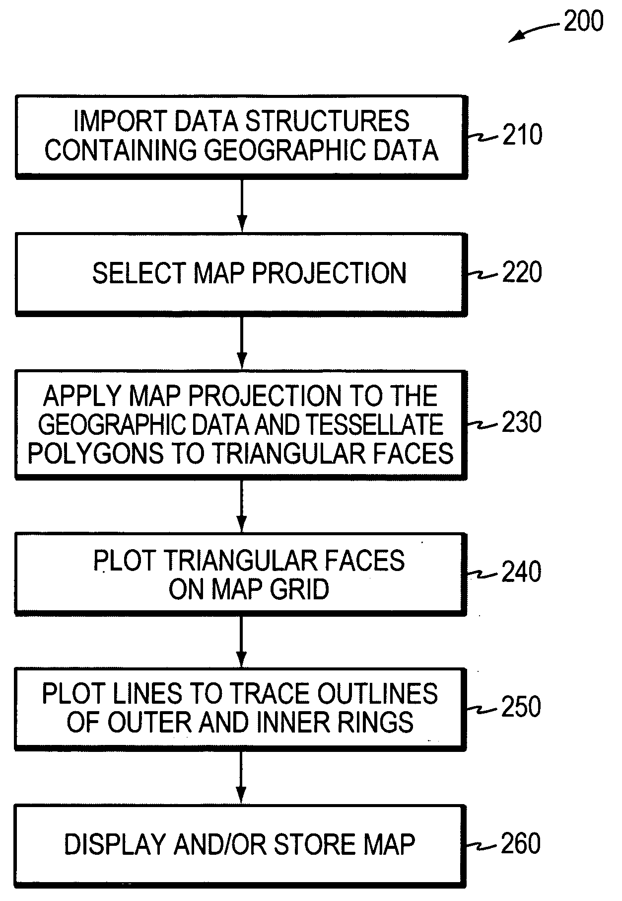

Image

  • Polygon trimming using a modified azimuthal map projection
  • Polygon trimming using a modified azimuthal map projection
  • Polygon trimming using a modified azimuthal map projection

Examples


Embodiment Construction

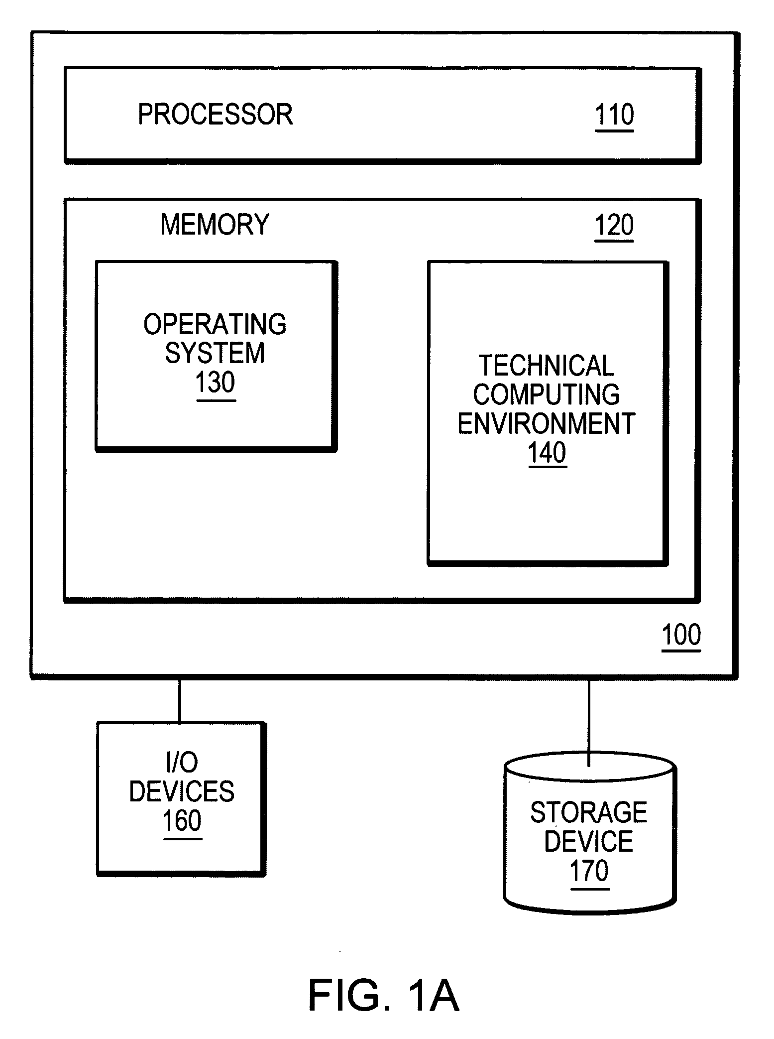
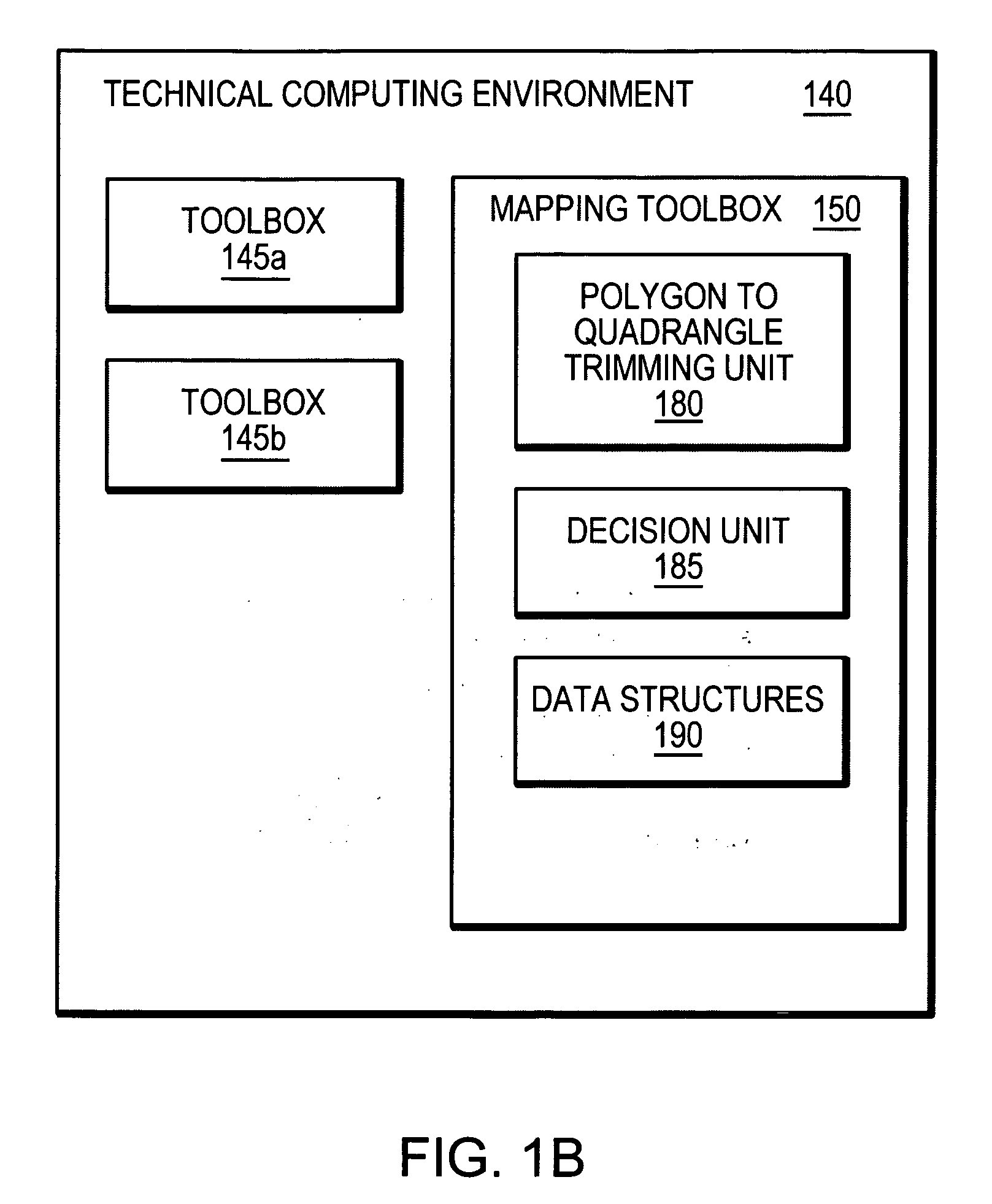
[0036]FIG. 1A is a block diagram of an example computer system 100 in which the polygon trimming techniques described herein may be employed. The computer system 100 includes a processor 110, such as a central processing unit (CPU), one or more storage devices 170 for storing computer-executable instructions, such as hard disks or compact disk (CD) drives, as well as one or more input / output (I / O) devices 160, such as keyboards, mice, network connections or monitors. The computer system 100 further includes a memory, for example a Random Access Memory (RAM) that, at least when the computer system is operating, may store computer-executable instructions. For example the memory may store instructions that implements an operating system 180, such as the Windows™ operating system available from Microsoft Corp., the OSX™ operating system available from Apple Computer Corp., or the Linux™ operating system available from a variety of vendors, including Red Hat Corp. of Raleigh, N.C., as we...


PUM


Abstract

In one embodiment, a system, method and computer readable media are disclosed for trimming geographic data that defines polygons to boundaries of a quadrangle. The geographic data is converted to map coordinates in a novel azimuthal map projection. Each map projected point in the azimuthal map projection has an azimuthal angle that is proportional to longitude of the point, and has a radius from the center of the azimuthal map projection that is proportional to both the longitude and latitude of the point. Polygons are trimmed along a lower limit of the quadrangle and along an upper longitude limit of the quadrangle using the azimuthal map projection. The map coordinates in the azimuthal map projection are then converted back to geographic data.

Description

BACKGROUND[0001]1. Technical Field[0002]This disclosure relates generally to trimming of polygon data.[0003]2. Background Information[0004]A map is a representation of geographic data, for example data that represents regions or features on a planet's surface, such as the Earth's surface. Geographic data specifies features in relation to geographic measure (i.e. georeferences the features) in 3-dimensional space, for example in relation to latitude (parallels) and longitude (meridians). Latitude is defined formally as the angle between the plane of the equator of a planet and a line normal to an idealized surface connecting a point in question to the planet's rotational axis. Longitude is defined formally as the angle at the center of a planet between two planes that align with, and intersect along, the axis of rotation, perpendicular to the plane of the equator. One plane contains the Prime Meridian and the other contains the point in question.[0005]To display a map on a two-dimens...

Claims


Application Information

Patent Timeline
Patent Type & Authority Applications(United States)
IPC IPC(8): G01C21/30
CPCG01C21/30
Inventor COMER, ROBERT P.
Owner THE MATHWORKS INC
Learn More