Method for Determining the Effects of the Wind on a Blind

a technology of wind and blinds, applied in the direction of sunshade, building components, structural/machine measurement, etc., can solve the problems of fabric unnecessarily retracted, blind damage may still be caused, etc., to eliminate the installation constraints of sensors and uniform sensor detection sensitivity

Active Publication Date: 2008-07-10
SOMFY ACTIVITES SA
View PDF10 Cites 11 Cited by
  • Summary
  • Abstract
  • Description
  • Claims
  • Application Information

AI Technical Summary

Benefits of technology

[0009]An object of the invention is to provide a method for determining the effects of the wind, obviating the abovementioned drawbacks and improving the methods known from the prior art. In particular, the invention proposes a method for determining the effects of the wind that makes it possible to eliminate the installation constrai

Problems solved by technology

Consequently, if the detection direction is parallel to the surface of the deployed fabric a force on the structure, generated by the wind, in a perpendicular direction will be scarcely if at all detected, wherea

Method used


Image

  • Method for Determining the Effects of the Wind on a Blind
  • Method for Determining the Effects of the Wind on a Blind
  • Method for Determining the Effects of the Wind on a Blind

Examples


first embodiment

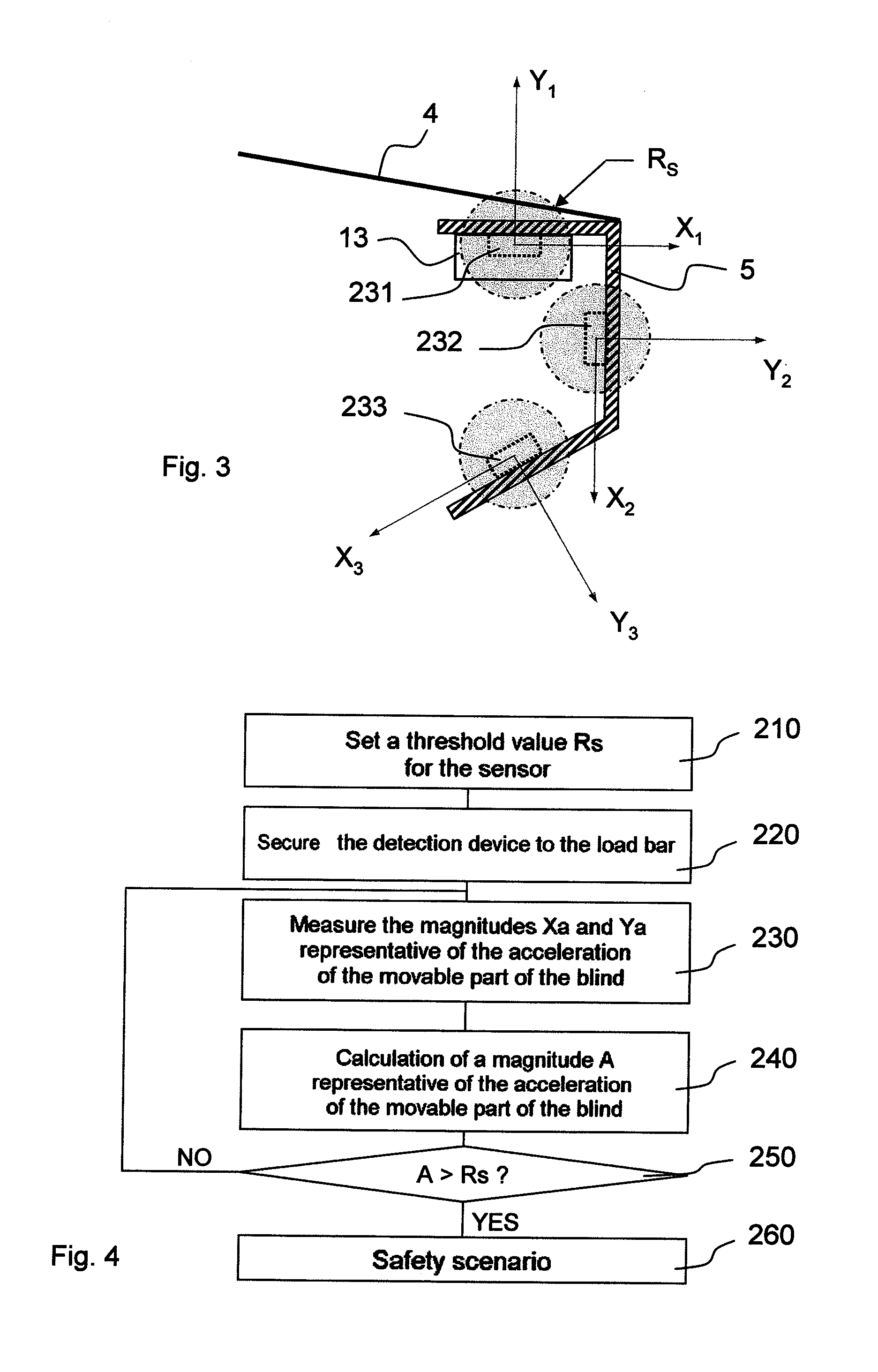
[0036]the determination method according to the invention is described below with reference to FIG. 4.

[0037]In a first step 210, a threshold value Rs is set in the detection device 13. It may be set by means of a potentiometer or by any other similar means. The threshold value is stored in the memory 25.

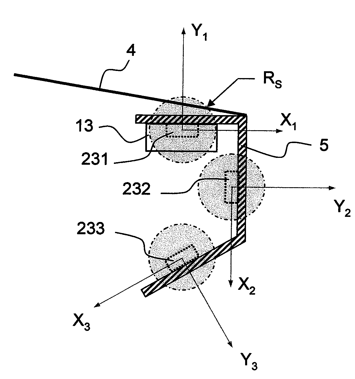
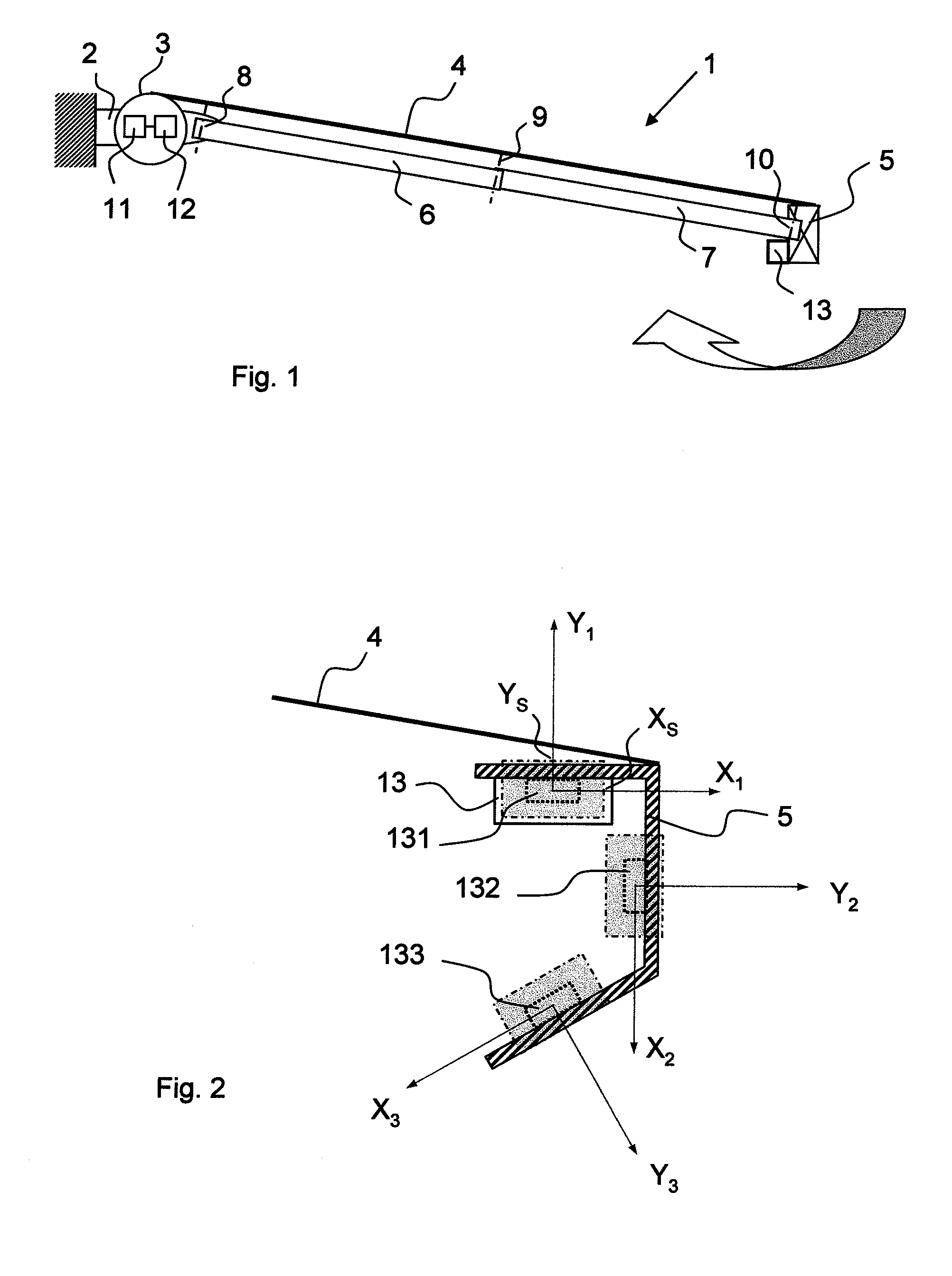
[0038]In a second step 220, the detection device is secured to the load bar. The order of this step and the preceding step may be reversed, but it is simpler to carry out the operations in the order suggested. Securing of the detection device is, for example, such that the sensor means it contains is in one of the positions of FIG. 3, i.e. the axes X1, Y1 and / or X2, Y2 and / or X3, Y3 of the sensor means 231 and / or 232 and / or 233 are parallel to (or at least substantially parallel to) one and the same plane P in which it is desired to measure the effects of the wind. In the case of FIG. 3, this plane P is perpendicular to the load bar 5. However, it is unimportant how the sensor means ...

second embodiment

[0046]the determination method according to the invention is described below with reference to FIG. 7.

[0047]In a first step 310, the detection device is secured to the load bar, as described for step 220. The configuration of the detection device is identical to that of FIG. 3. However, a learning phase is necessary here.

[0048]In a second step 320, the installer performs a configuration operation that makes it possible to associate a specific OXY reference, for example an orthogonal reference, with the sensor means. Setting of this new OXY reference is thus independent of the detection axes X1 and Y1 of the sensor means. It is thus independent of the orientation of the detection device. The fact that this reference is taken into account by the detection device is reflected in a relationship between the new OXY reference and a reference OX1Y1 corresponding to the detection axes of the sensor (rotation through an angle α).

[0049]In order to define this specific reference, different lea...


PUM


Abstract

A method for determining the effects of the wind on a blind (1) or the like that is provided with a sensor means (231) for measuring the effects of the wind in a first measurement direction (X1) and in a second measurement direction (Y1), the two directions being different, the method comprising the following steps:
    • collecting, from the sensor means, a first signal representative of the effects of the wind on the blind or the like, in the first measurement direction;
    • collecting, from the sensor means, a second signal representative of the effects of the wind on the blind or the like, in the second measurement direction;
which comprises the step of:
  • processing these signals so as to provide a secondary signal representative of the effects of the wind and independent of the orientation of the sensor means in a plane defined by the two directions, in order to obtain uniform sensor detection sensitivity irrespective of the orientation of the sensor.
  • Description

    [0001]The invention relates to a method for determining the effects of the wind on a blind or the like and to a device for protecting a blind or the like against the effects of the wind.BACKGROUND OF THE INVENTION[0002]Manufacturers seek to protect blinds against the effects of the wind. Indeed, when the wind blows in gusts, the fabric of the blind offers great resistance to the wind and places extreme stresses on the structure of the blind. The blind may thus be damaged. It should be noted that damage to the blind is greater when a force is applied substantially perpendicularly to the surface of the deployed fabric. Furthermore, from a safety standpoint, it is essential for the blind to remain securely fastened to the structure of the building to which it is fitted. Standard EN13561 specifies, further, the constraints to be complied with.[0003]In response to this requirement, a known solution consists in measuring the vibration of the movable components, i.e. the arms or, more comm...

    Claims


    Application Information

    Patent Timeline
    IPC IPC(8): G01P15/00G01M99/00
    CPCE04F10/0618E04F10/0659E05F15/71E06B2009/6863E05Y2800/40E04F10/0692E05Y2900/106E05Y2900/00
    Inventor LAPIERRE, STEPHANE
    Owner SOMFY ACTIVITES SA
    Why Eureka
    Try Eureka