
Centrifugal fraction collection system and method

a fraction and centrifugal technology, applied in the field of centrifugal can solve the problems of inefficient fraction collection system and method, large amount of solvent, long elution time, etc., and achieve the effect of convenient use and inexpensiveness

Inactive Publication Date: 2008-07-10
BANK OF AMERICA NAT TRUST & SAVINGS ASSOC
View PDF23 Cites 11 Cited by
  • Summary
  • Abstract
  • Description
  • Claims
  • Application Information

AI Technical Summary

Benefits of technology

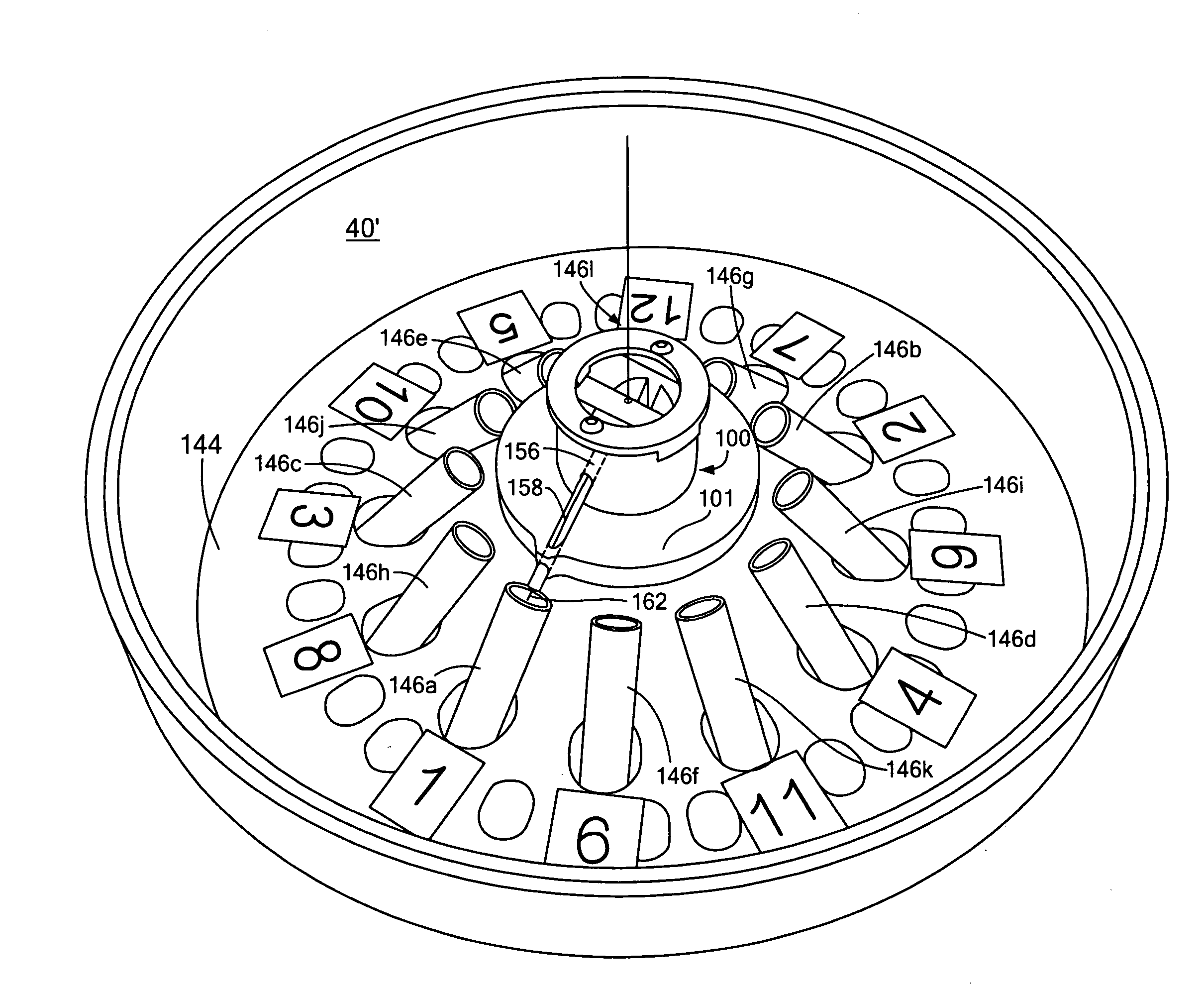
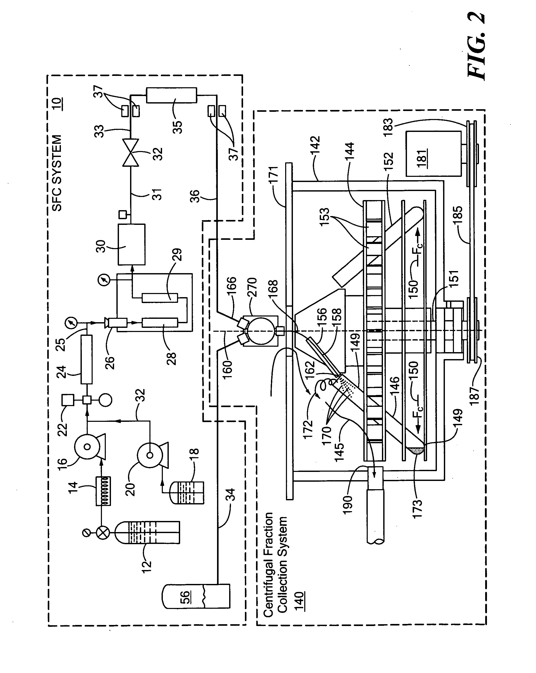
"The invention is a centrifugal fraction collection system and method that is easy to use, inexpensive, compact, and can be integrated with existing SFC systems. The system includes a rotating carrier for holding sample collection containers and inducing a centrifugal force. A flexible eluant tube is disposed over the rotating carrier and through a guide for receiving a flow of eluant and directing it into the sample collection containers. The system separates non-volatile compounds from volatile compounds based on their respective densities and collects the non-volatile compounds in the desired collection container. The system is small relative to the number of fraction collection containers and does not require a pressurized environment. The technical effects of the invention include improved fraction resolution, higher sample recovery, and a more robust and user-friendly system."

Problems solved by technology

However, a drawback to the use of HPLC is the fact that in many instances long elution times, as well as large of amounts of solvents are required for the process.
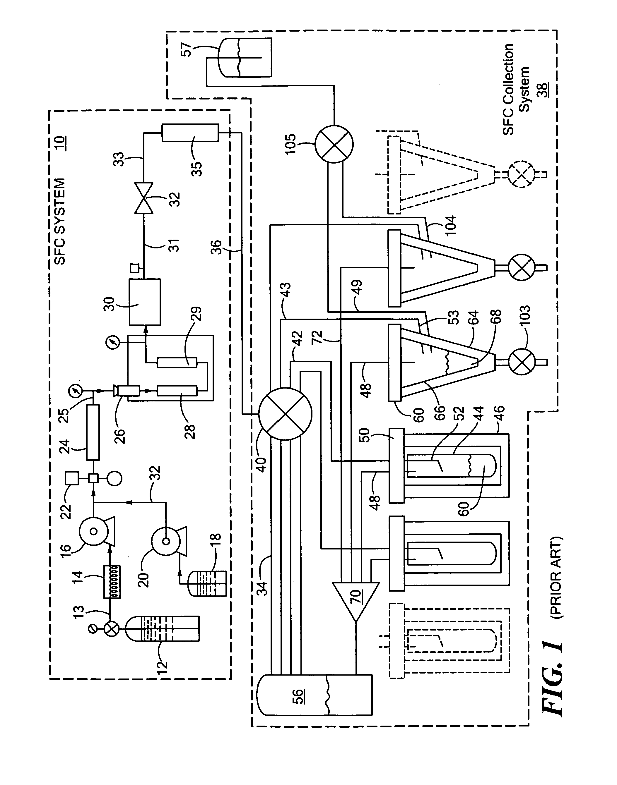
While there are several mechanisms for analyte collection in SFC disclosed in the aforementioned patents, the collection systems and methods disclosed therein inefficiently collect fractions, are typically large, complex, difficult to operate, expensive, do not operate at room temperature and standard pressure, typically have a small number of collection tubes, and often require a chemical fume hood.

Method used


Image

  • Centrifugal fraction collection system and method
  • Centrifugal fraction collection system and method
  • Centrifugal fraction collection system and method

Examples


Embodiment Construction

[0046]Aside from the preferred embodiment or embodiments disclosed below, this invention is capable of other embodiments and of being practiced or being carried out in various ways. Thus, it is to be understood that the invention is not limited in its application to the details of construction and the arrangements of components set forth in the following description or illustrated in the drawings. If only one embodiment is described herein, the claims hereof are not to be limited to that embodiment. Moreover, the claims hereof are not to be read restrictively unless there is clear and convincing evidence manifesting a certain exclusion, restriction, or disclaimer.

[0047]Although specific features of the invention are shown in some drawings and not in others, this is for convenience only as each feature may be combined with any or all of the other features in accordance with the invention. The words “including”, “comprising”, “having”, and “with” as used herein are to be interpreted b...


PUM

PropertyMeasurementUnit
temperatureaaaaaaaaaa
angleaaaaaaaaaa
angleaaaaaaaaaa

Abstract

A centrifugal fraction collection system including a rotating carrier for holding at least one sample collection container and inducing a centrifugal force, a guide disposed on the rotating carrier, and a flexible eluant tube disposed over the rotating carrier and through the guide for receiving a flow of eluant having volatile and non-volatile components and directing the flow of eluant into at least one sample collection container wherein the centrifugal force separates the non-volatile and volatile components based on their respective densities and collects the non-volatile components in at least one sample collection container.

Description

RELATED APPLICATIONS[0001]This application claims benefit of and priority of U.S. Provisional Patent Application Ser. No. 60 / 879,385, filed Jan. 9, 2006, incorporated by reference herein.FIELD OF THE INVENTION[0002]This invention relates to a centrifugal fraction collection system and method.BACKGROUND OF THE INVENTION[0003]The use of supercritical fluids in industrial processes has been growing at an ever-quickening pace. Replacing traditional, often hazardous and flammable, organic solvents with supercritical fluids has been a prime area of research. Carbon dioxide is a popular choice due to the fact that it is nontoxic, nonflammable, and inexpensive. An attractive feature of a supercritical fluid is that its density can be varied simply by changing the pressure or temperature. Therefore, all density-dependent properties, such as dielectric constant and solubility parameter, can be manipulated in this manner. These key features of supercritical fluids make them ideal candidates fo...

Claims


Application Information

Patent Timeline
Patent Type & Authority Applications(United States)
IPC IPC(8): B01D21/26B01D15/08B04B11/06B04B13/00
CPCB01D1/14B01D15/247B01D15/40B04B5/0414B01D2221/10B04B13/00G01N30/82B01D21/262B04B11/06
Inventor HEDBERG, HERBERT J.
Owner BANK OF AMERICA NAT TRUST & SAVINGS ASSOC
Learn More