System and method for multi-pulse laser processing

a laser processing and multi-pulse technology, applied in the direction of manufacturing tools, semiconductor/solid-state device details, welding/soldering/cutting articles, etc., can solve the problems of unfavorable solution and unstable pulse energy, and achieve the effect of preventing significant energy and stable operation

Inactive Publication Date: 2008-07-10
ELECTRO SCI IND INC
View PDF20 Cites 25 Cited by
  • Summary
  • Abstract
  • Description
  • Claims
  • Application Information

AI Technical Summary

Benefits of technology

[0008]The invention generally provides for adjusting laser pulse timing with respect to impingement intervals that are aligned with respect to microstructures such that the pulses may either impinge a desired target on the microstructure, or not impinge the microstructure.
[0009]In accordance with an embodiment, the invention provides a stabilized system for laser-based processing a workpiece. The system includes one or more laser sources to generate laser pulses, at least some of the pulses being closely spaced in time. The system also includes an optical switch that provides impingement intervals and non-impingement intervals in response to one or more control signals, wherein a laser pulse present during an impingement interval is allowed to propagate to a workpiece location. The system also includes a controller that is coupled to the laser and optical switch to either allow a pulse to propagate to the workpiece if a pulse is desired, or to time shift a pulse to a non-impingement interval if a pulse is not desired, the time shift being sufficiently small to maintain stable operation, and sufficiently large to prevent significant energy from impinging the workpiece (as a result of the finite response time of the optical switch).

Problems solved by technology

Intermittent pulsing, however, may generally lead to unstable pulse energy.
This however, is not a preferred solution.

Method used


Image

  • System and method for multi-pulse laser processing
  • System and method for multi-pulse laser processing
  • System and method for multi-pulse laser processing

Examples


Embodiment Construction

[0011]The following description may be further understood with reference to the accompanying drawings in which:

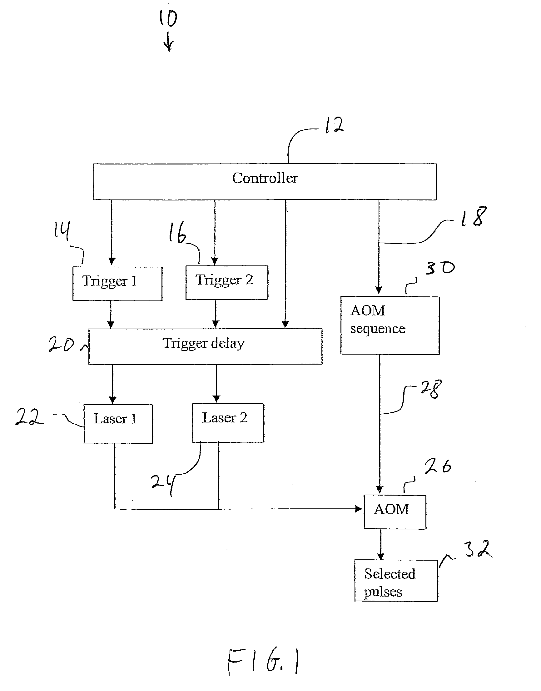
[0012]FIG. 1 shows an illustrative schematic diagram showing pulse timing control and timing AOM control;

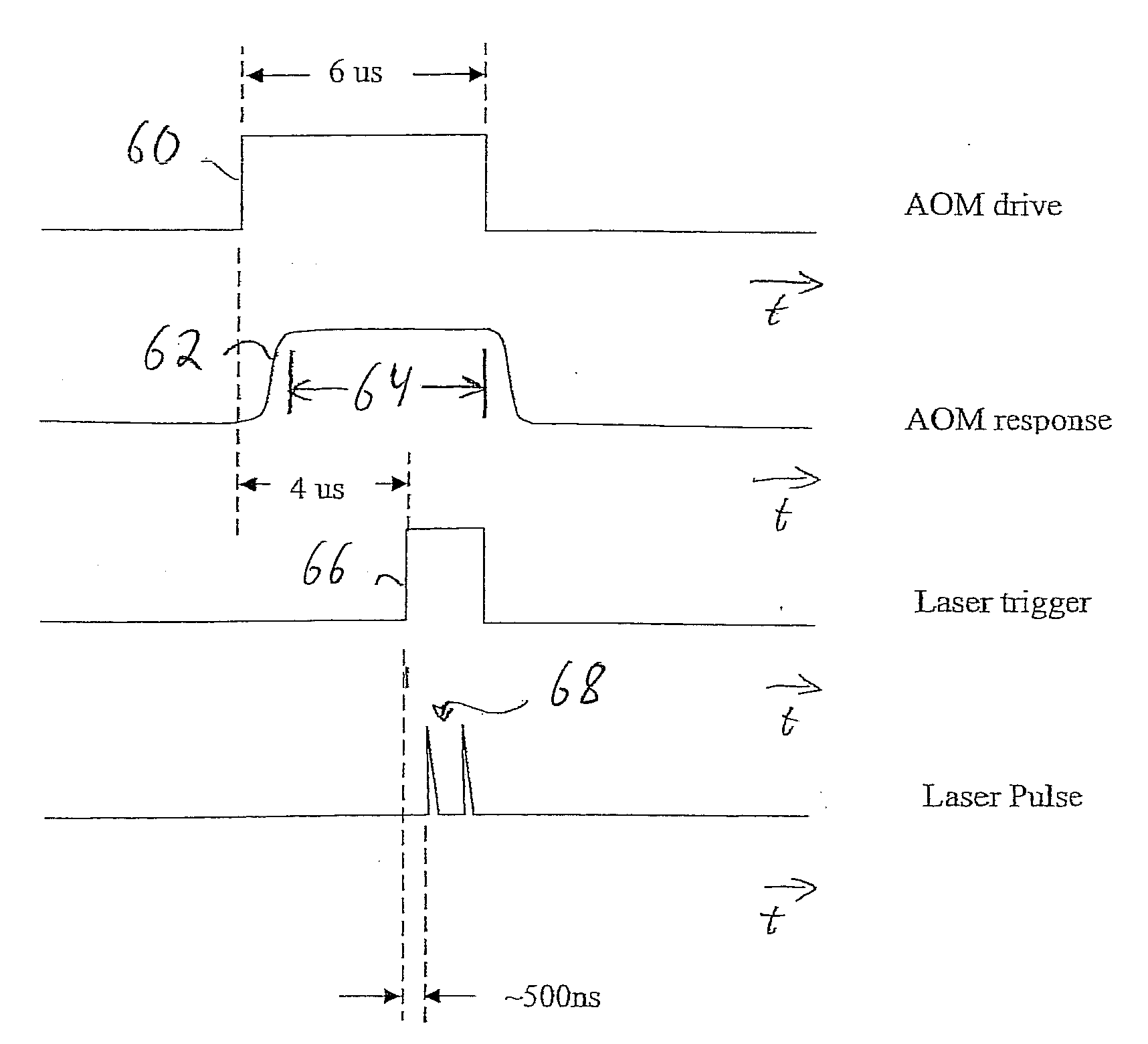
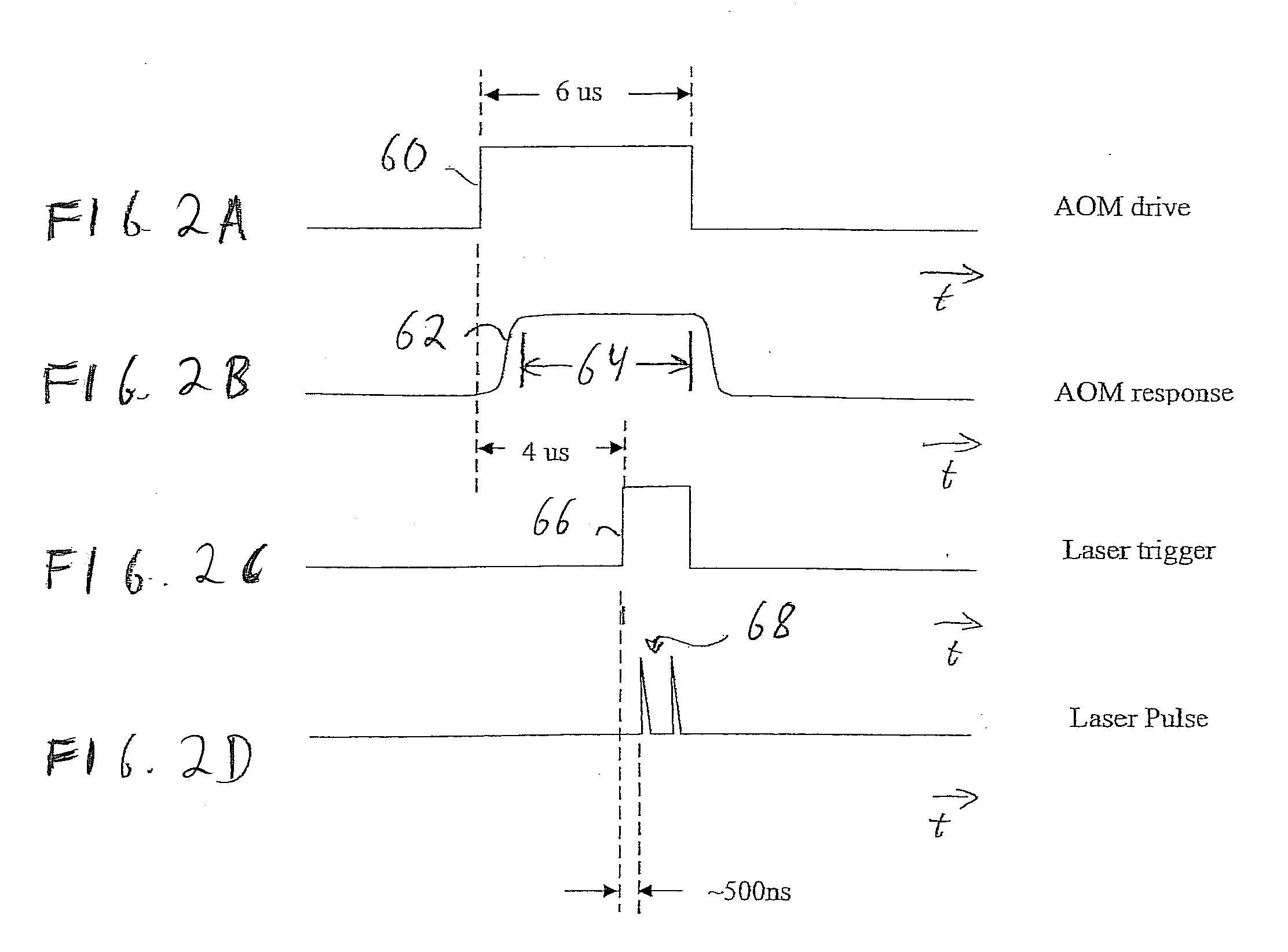
[0013]FIGS. 2A-2D show illustrative graphical views of an AOM command, an AOM response, a laser trigger, and a pair of pulses in a system in accordance with an embodiment of the invention;

[0014]FIGS. 3A-3C show illustrative graphical views of an optical response to a selective AOM command, and corresponding groups of laser pulses and selected pulses in a system in accordance with a further embodiment of the invention;

[0015]FIGS. 4A-4C show illustrative graphical views of an optical response to an AOM command sequence, and corresponding groups of laser pulses and selected pulses in a system in accordance with a further embodiment of the invention;

[0016]FIGS. 5A-5C show illustrative graphical views of an optical response to a AOM command sequence, and corresponding groups ...


PUM

PropertyMeasurementUnit
timeaaaaaaaaaa
timeaaaaaaaaaa
timeaaaaaaaaaa

Abstract

Laser pulses are selected from a group of closely spaced laser pulses with an optical modulator by adjusting pulse timing relative to an impingement interval. An adjusted pulse is moved from an impingement interval to a non-impingement interval and is blocked. The blocked laser source is stabilized by running nearly continuously. Pulse selection with multiple laser sources is achieved with a single acousto-optic modulator.

Description

PRIORITY[0001]This application claims priority to U.S. Provisional Patent Application Ser. No. 60 / 883,583, filed Jan. 5, 2007.BACKGROUND[0002]The present invention generally relates to laser processing systems as disclosed, for example, in U.S. Pat. Nos. 6,559,412; 5,812,569; 5,998,759; 6,339,604; 6,727,458; and 6,541,731 as well as U.S. Patent Application Publication Number No. 2002 / 0167581, each of which is assigned to the assignee of the present invention, and each of which is hereby incorporated by reference in its entirety. Laser based micromachining for memory repair of integrated circuits, for example, is disclosed in LIA Handbook of Laser Materials Processing, by John Ready, Laser Institute of America, Mongolia Publishing Co., Inc. (2001), chapter 19.[0003]The above mentioned laser processing systems are generally used for a variety of micromachining tasks including, for example, blowing links of integrated circuits to repair memory devices. In such laser processing systems,...

Claims


Application Information

Patent Timeline
Patent Type & Authority Applications(United States)
IPC IPC(8): B23K26/08B23K26/06B23K26/0622H01L21/48H01L21/768
CPCB23K26/0604H01L23/5258B23K26/409B23K26/0635H01L2924/0002B23K26/0624B23K26/40B23K2103/172H01L2924/00
Inventor CORDINGLEY, JAMESMALTSEV, DIMITRYPLOTKIN, MICHAEL
Owner ELECTRO SCI IND INC
Why Eureka
Try Eureka