Wireless sensing device and wireless network sensing system

a wireless network and sensing device technology, applied in the field of sensing devices and wireless network sensing systems, can solve the problems of limited amount inability to manufacture common communication interfaces, and limited range of conventional wireless sensing systems b>2/b>, so as to facilitate system integration, facilitate system expansion, and enhance product compatibility

Inactive Publication Date: 2008-07-10
DELTA ELECTRONICS INC
View PDF3 Cites 4 Cited by
  • Summary
  • Abstract
  • Description
  • Claims
  • Application Information

AI Technical Summary

Benefits of technology

[0012]As mentioned above, a wireless communication signal is transmitted or received in the wireless sensing device and the wireless network sensing system according to the invention. The wireless communication signal satisfies the universal wireless communication protocol, such as IEEE 802.15.4 protocol, so as to facilitate the system integration and the enhancement of the product compatibility. Compared with the related art, the invention satisfies the universal wireless communication protocol, so the invention has the advantages that the device and the system can be easily expanded, can resist the signal interference and can perform the bi-directional communication so that the overall efficiency can be enhanced. In addition, the wireless sensing device monitors the power state by the power-monitoring module so that the usage efficiency and the product reliability can be enhanced.

Problems solved by technology

Therefore, the problems of system integration and product compatibility always exist so that a common communication interface cannot be manufactured.
In addition, the conventional wireless sensing system 2 is usually limited to the peer-to-peer relationship or is only limited to the single peer to multiple peers application.
In addition, the conventional wireless sensing system 2 can only support limited amounts of wireless sensing devices 1.
This is because the server 21 may have the heavy loading, thereby causing the system to become unstable and increasing the cost.
In addition, because the wireless communication interface is developed by the manufacturers themselves, the wireless signal transmitted by the wireless sensing device 1 often interferes with other signals by other electronic apparatuses, thereby increasing the signal error rate.

Method used


Image

  • Wireless sensing device and wireless network sensing system
  • Wireless sensing device and wireless network sensing system
  • Wireless sensing device and wireless network sensing system

Examples


Embodiment Construction

[0018]The present invention will be apparent from the following detailed description, which proceeds with reference to the accompanying drawings, wherein the same references relate to the same elements.

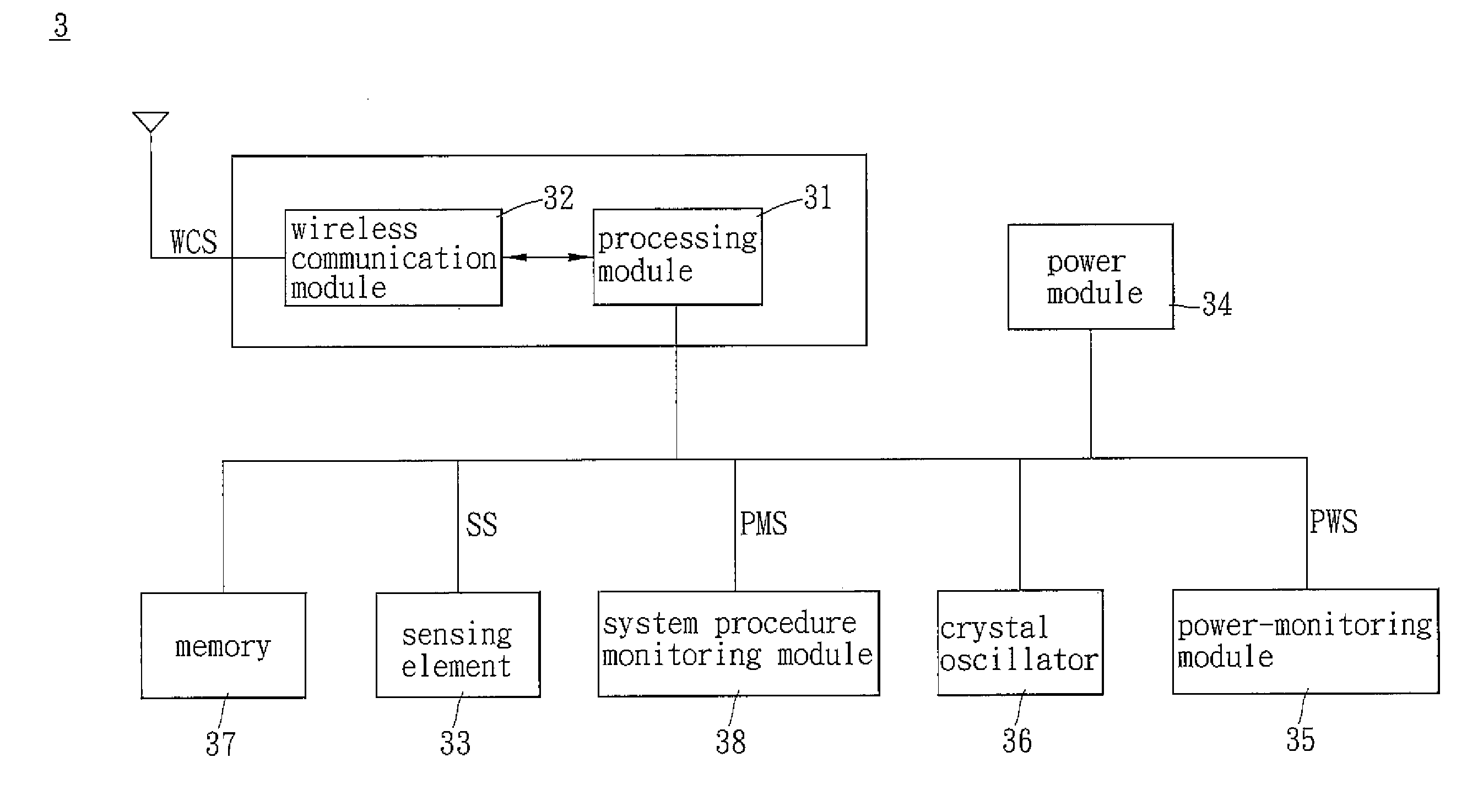
[0019]Referring to FIG. 3, a wireless sensing device 3 according to an embodiment of the invention includes a processing module 31, a wireless communication module 32, at least one sensing element 33, a power module 34 and a power-monitoring module 35.

[0020]The wireless communication module 32 is electrically connected with the processing module 31 to transmit or receive a wireless communication signal WCS. In this embodiment, the wireless communication module 32 can be implemented by a base band circuit and a radio frequency (RF) circuit. The base band circuit mainly provides connection establishment and elimination, signal encoding, packet processing and frequency hopping control. The radio frequency circuit mainly provides carrier synthesis, signal reception and signal transmission...


PUM


Abstract

A wireless sensing device includes a processing module, a wireless communication module, at least one sensing element, a power module and a power-monitoring module. The wireless communication module is electrically connected with the processing module to transmit or receive a wireless communication signal. The sensing element is electrically connected with the processing module to transmit a sensing signal to the processing module. The power module is electrically connected with and supplies a power to the processing module the wireless communication module and the sensing element. The power-monitoring module is electrically connected with the processing module and the power module to transmit a power-monitoring signal to the processing module.

Description

CROSS REFERENCE TO RELATED APPLICATIONS[0001]This Non-provisional application claims priority under 35 U.S.C. §119(a) on Patent Application No(s). 096100440 filed in Taiwan, Republic of China on Jan. 5, 2007, the entire contents of which are hereby incorporated by reference.BACKGROUND OF THE INVENTION[0002]1. Field of Invention[0003]The invention relates to a sensing device and a sensing system and, in particular, to a wireless sensing device and a wireless network sensing system.[0004]2. Related Art[0005]Sensing devices have been widely used in industries nowadays. For example, a temperature sensing device is utilized to monitor an environmental temperature, a humidity sensing device is utilized to monitor an environmental humidity and an optical sensing device is utilized to monitor an environmental brightness. Arranging the sensing devices at different positions can construct a sensing system or a monitoring system for monitoring the environment so as to warn unpredictable proble...

Claims


Application Information

Patent Timeline
Patent Type & Authority Applications(United States)
IPC IPC(8): G01W1/00
CPCH04Q2209/43H04Q9/00
Inventor TANG, MIN-TSUNGLIU, SU-FEN
Owner DELTA ELECTRONICS INC
Why Eureka
Try Eureka