Material property detecting method and device based on grating effect of standing wave excitation transient body

A technology for material characteristics and detection devices, which is applied in measurement devices, material analysis by optical means, and material analysis, etc., can solve the problem that the optical path adjustment error has a great influence on the grating characteristics, the optical path is complicated, and the stability and reliability of the detection system are adversely affected. And miniaturization and other issues, to achieve the effect of simple optical path, stable grating characteristics, and reduced power level requirements

Active Publication Date: 2013-02-27
合肥利弗莫尔仪器科技有限公司
View PDF7 Cites 4 Cited by
  • Summary
  • Abstract
  • Description
  • Claims
  • Application Information

AI Technical Summary

Problems solved by technology

The advantage of this method is that the period of the transient grating can be adjusted by adjusting the angle of the two beams of light, which has strong flexibility in measurement; the disadvantage is that the optical path is relatively complicated, and the adjustment error of the optical path has a great influence on the characteristics of the grating. Therefore, it is not conducive to the stability, reliability and miniaturization of the detection system in practical applications.

Method used


Image

  • Material property detecting method and device based on grating effect of standing wave excitation transient body
  • Material property detecting method and device based on grating effect of standing wave excitation transient body
  • Material property detecting method and device based on grating effect of standing wave excitation transient body

Examples


Embodiment Construction

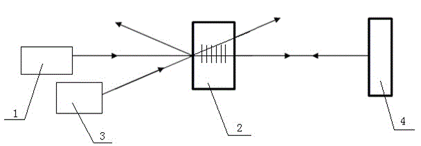
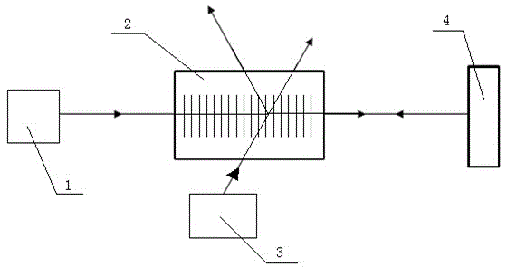
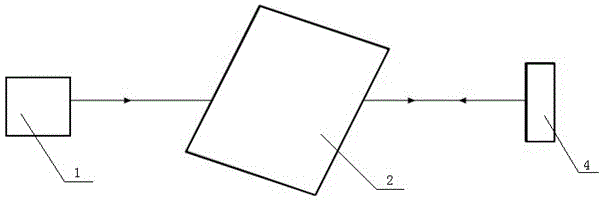
[0031] A material property detection method based on standing wave excitation transient volume grating effect, comprising the following steps:

[0032] (1) First, the pump light source 1 is used to emit a pump beam to the surface of the tested sample 2. The pump beam enters the inside of the tested sample 2 and finally exits from the back of the tested sample 2. The emitted pump beam is set on the surface of the tested sample The reflection of the high-reflectivity mirror 4 at the back end of the test sample 2 reenters the interior of the test sample 2 to overlap with the initial incident pump beam, and a standing wave is formed in the overlapping area due to the optical interference effect, resulting in a periodic light intensity distribution. When the periodic light intensity distribution interacts with the measured sample material, it will produce periodic spatial modulation on the measured sample material properties, forming a transient volume grating;

[0033] (2) The det...


PUM


Abstract

The invention discloses a material property detecting method and device based on a grating effect of a standing wave excitation transient body. The method comprises the following steps that firstly a pump beam is reflected by a reflective device after penetrating a detected sample and re-enters to the detected sample to overlap the initial incident pump beam; standing wave is formed due to optical interference effect, periodic light intensity distribution is produced, transient body grating is formed, and a probe beam is incident to the transient body grating area of the detected sample; the final detecting beam is divided into a diffracted beam and a transmitted beam due to the diffraction effect of the transient body grating; and the relevant properties of the detected sample material is obtained through detecting the strength and phase of the diffracted beam or transmitted beam and the change thereof along time. According to the method and device provided by the invention, the light path is simple, the transient grating property is stable; the system beneficial for relevant analyzing detectors is integrated and miniaturized in actual application, so that better reliability and stability are obtained; and the method and device can be used for multiple fields such as photothermal detection, photoaccoustic diction, semiconductor dynamic conveying property detection, photothermal biological and medical detection, photothermal and spectrometric detection, nonlinear optical properties detections of optical materials and the like.

Description

[0001] technical field [0002] The invention relates to the laser excitation transient grating effect and its application field, in particular to a material characteristic detection method and device based on the standing wave excitation transient volume grating effect. Background technique [0003] The laser-induced transient grating technique (the laser-induced transient grating technique) is widely used in the research and analysis of the properties of various materials, especially the photothermal response, photoacoustic effect, relaxation and transport properties, and nonlinear optical properties of materials. etc. research and analysis. [0004] The basic principle of laser-excited transient grating technology can be described as follows: two coherent laser beams (usually called pump light) overlap on the surface or inside of the material, and due to optical interference effects, periodic light will be generated in the overlapping area of ​​the two beams Intensity di...

Claims


Application Information

Patent Timeline
Patent Type & Authority Applications(China)
IPC IPC(8): G01N21/17
Inventor 吴周令陈坚黄明
Owner 合肥利弗莫尔仪器科技有限公司
Why Eureka
Try Eureka