

Electronic Pen Device
a technology of electronic pen and electronic pen, which is applied in the direction of mechanical pattern conversion, instrumentation, cathode-ray tube indicator, etc., can solve the problems of reducing the signal to noise ratio in the detected signal, reducing accuracy and resolution, and significant attenuation of the detected signal detected by the receiver, so as to prevent system damage, accurate signal, and efficient operation
- Summary
- Abstract
- Description
- Claims
- Application Information
AI Technical Summary
Benefits of technology
Problems solved by technology
Method used
Image

Examples
Embodiment Construction
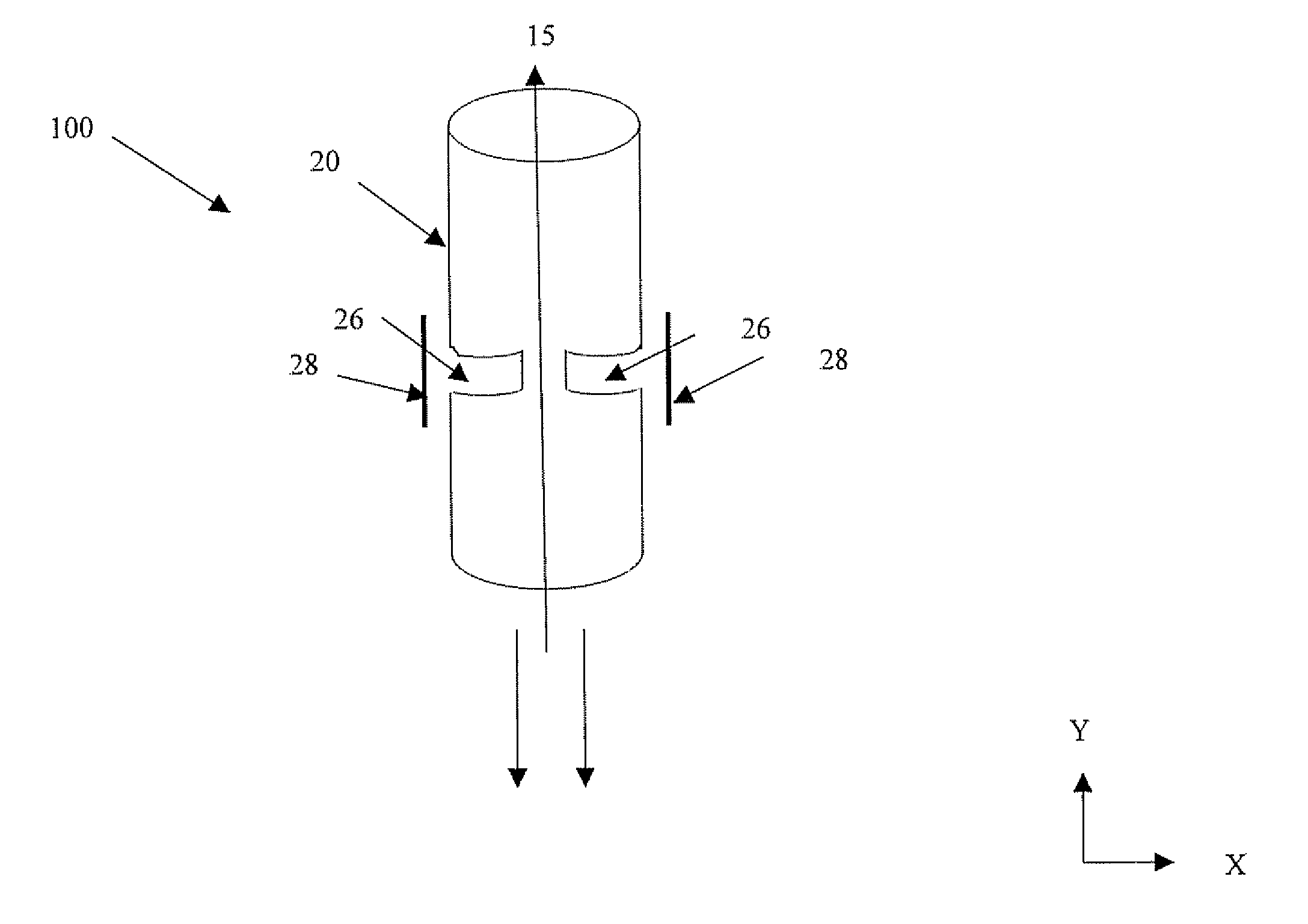
[0062]The following description is provided, alongside all chapters of the present invention, so as to enable any person skilled in the art to make use of said invention and sets forth the best modes contemplated by the inventor of carrying out this invention Various modifications, however, will remain apparent to those skilled in the art, since the generic principles of the present invention have been defined specifically to provide a pen device, which can be used for digitizing graphical or textual data drawn on every writing surface.
[0063]All references cited herein are incorporated by reference in their entirety. Citation of a reference does not constitute an admission that the reference is prior art.
[0064]In the description and claims of the present application, each of the verbs, “comprise”“include” and “have”, and conjugates thereof, are used to indicate that the object or objects of the verb are not necessarily a complete listing of members, components, elements or parts of ...
PUM
 Abstract
Description
Claims
Application Information