
Memory sharing mechanism based on priority elevation

a memory sharing and priority elevation technology, applied in the field of communication systems, can solve the problems of inability to implement economically, delay in the same amount of flow control signals that are returned by the switch to the port adapter, and high cost of the switch-internal buffer, so as to achieve easy and effective implementation, less memory, and easy tolerability

Inactive Publication Date: 2008-07-10
INT BUSINESS MASCH CORP
View PDF11 Cites 10 Cited by
  • Summary
  • Abstract
  • Description
  • Claims
  • Application Information

AI Technical Summary

Benefits of technology

The present invention provides a communication device for transporting packets of data with priority elevation. The device includes a memory for storing the packets and a priority modification unit for assigning higher priorities to packets that are causing congestion within the memory. The priority modification unit can elevate the priority of the packets by starting or stopping their modification. The device can also include a priority elevation detection unit that initiates priority elevation information based on the memory state information and the number of priority packets. The invention allows for faster and easier switching between priority elevation mode and normal operating mode, and reduces the amount of memory needed. The invention also allows for remote priority elevation information to be sent based on the memory state information and the number of priority packets. The invention helps to resolve blocking problems and allows for efficient use of memory space.

Problems solved by technology

However, switch-internal buffers are expensive since they demand memory with a multiple of the port bandwidth.
At very high speeds, the delay of these long cables may become a multiple of a packet time duration and causes each packet to arrive at the switch buffer several packet times after it has been sent from the input queue.
Similarly, any flow-control signals that are returned by the switch to the port adapters also arrive there delayed by the same amount of time.
Assuming, for example, an n×n switch with n=64 ports, P=8 priorities and cable lengths of >30 m at port speeds of 40 Gb / s, the total switch memory size of n2·P·RTT would be so large that current CMOS technology does not allow an economic implementation.
As traffic behavior is not predictable, this waste of memory is not practical for practical communication devices, e.g., NPs (network processors) and switches.

Method used


Image

  • Memory sharing mechanism based on priority elevation
  • Memory sharing mechanism based on priority elevation
  • Memory sharing mechanism based on priority elevation

Examples


Embodiment Construction

[0032]In the following the embodiments of the invention are addressed. The number of modules and units is chosen for sake of example only and can be varied without leaving the scope of the invention. For sake of clarity in FIGS. 1 to 3 for a number of identical units arranged in parallel only some of these units are depicted.

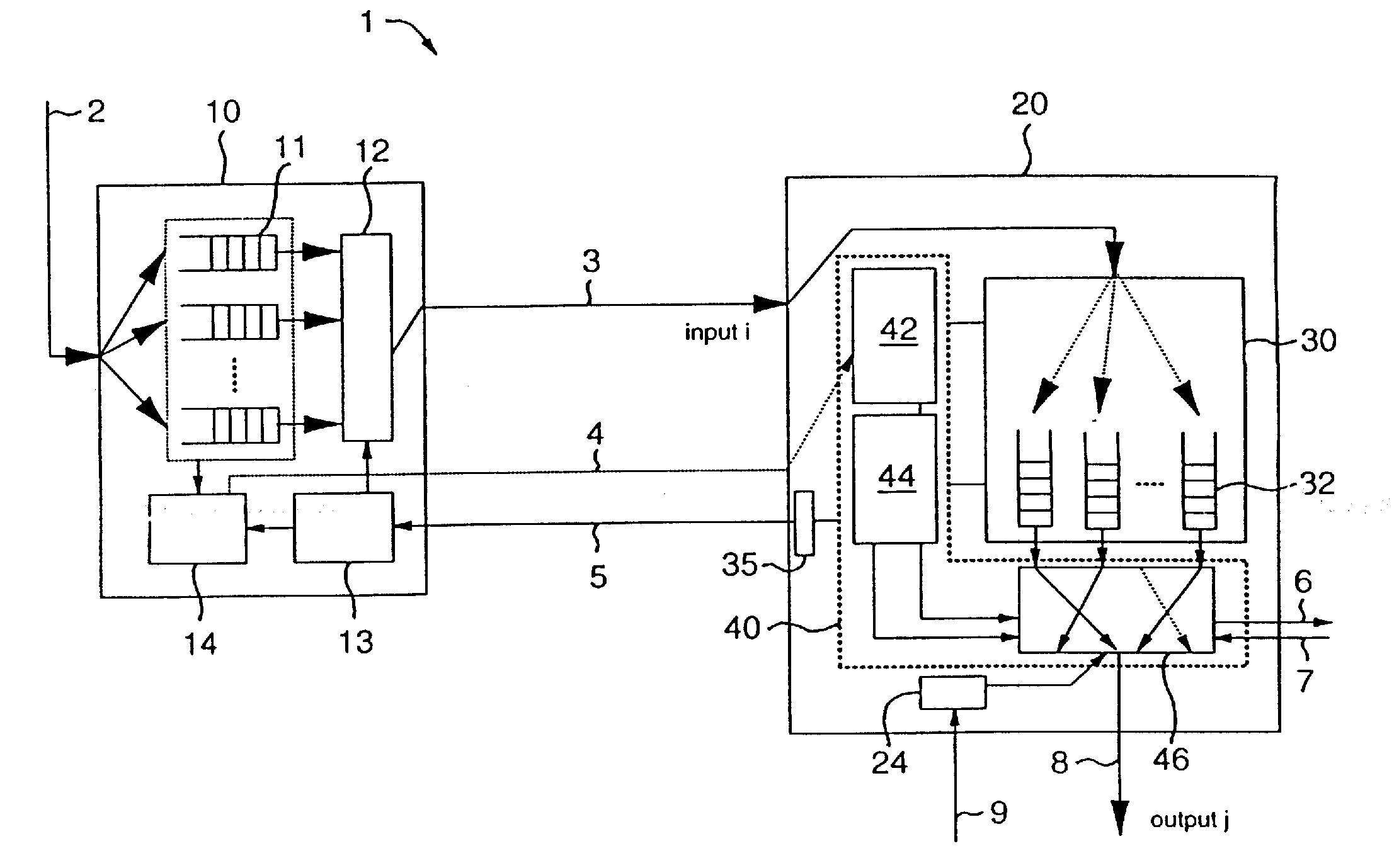
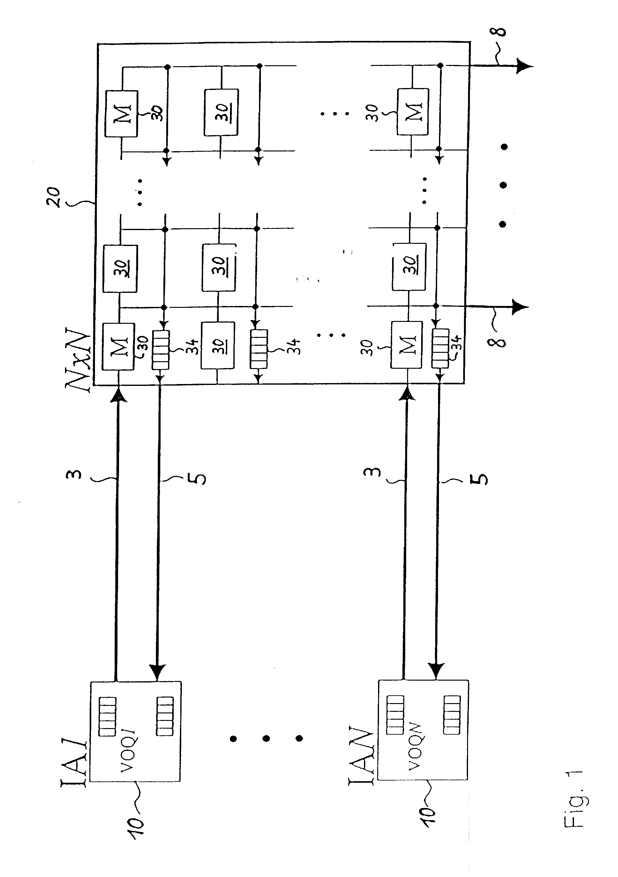
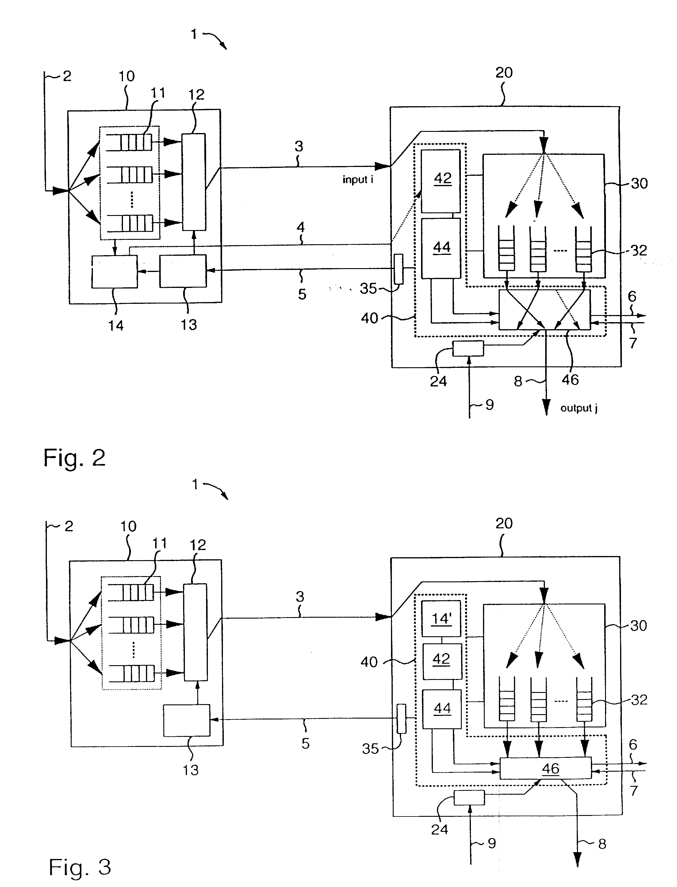
[0033]Before an embodiment of the present invention is described, a schematic illustration of a switch arrangement of the state of the art is addressed. FIG. 1 shows a communication or switching device 20 that is connected via connecting means 3, 5 to an input adapter 10 and via switching device outputs 8 to output adapters or other communication units, which for the sake of simplicity are not shown. Each input adapter 10 comprises virtual output queues (VOQN), hereafter referred to as queue units. The switching device 20 has a memory 30 that here comprises memory units 30, also labeled with M, which can be shared. These memory units 30 are arranged within a mat...


PUM


Abstract

The present invention discloses a memory sharing mechanism based on priority elevation. In accordance with the present invention, there is provided an apparatus and method for transporting packets of data in a communication device, wherein each packet is assigned one of several priorities and received based on memory state information. The method comprises the steps of storing the received packets in a memory and modifying the assigned priority of any of the packets causing congestion within the memory.

Description

TECHNICAL FIELD[0001]The present invention relates to a communication system for transporting packets of data, particularly where the packets are transported with an assigned priority. More particularly the invention relates to a communication device, e.g. a switch, that receives packets based on memory state information. Further, the invention relates to a method for transporting packets of data in the communication device. The invention is also related to an input adapter for transporting packets of data to the communication device.DESCRIPTION OF PRIOR ART[0002]The popularity of the World Wide Web and its annual increase in size requires increasingly larger and faster switching fabrics, also referred to as switching devices or switches. To meet today's switching requirement of 1 Tb / s throughput and above, switches are growing not only in terms of port speed, but also in number of ports. With 5 Gb / s links, port sizes of 64, and today's link and fabrication technologies, multi-chip ...

Claims


Application Information

Patent Timeline
Patent Type & Authority Applications(United States)
IPC IPC(8): H04L12/56
CPCH04L47/10H04L47/2433H04L49/90H04L47/30H04L47/6215H04L47/2458
Inventor ABEL, FRANCOIS G.DENZEL, WOLFGANGENGBERSEN, ANTONIUSGRAMSAMER, FERDINANDGUSAT, MITCHLUIJTEN, RONALD P.MINKENBERG, CYRIELVERHAPPEN, MARK
Owner INT BUSINESS MASCH CORP
Learn More