Compressed memory architecture for embedded systems

a memory architecture and embedded system technology, applied in the field of memory architectures, can solve the problems of insufficient memory savings for additional compression hardware, small hardware size, and complex functionality of embedded system design, and achieve the effects of reducing memory usage, fast compression speed, and reducing memory consumption

Inactive Publication Date: 2007-11-27
NEC CORP
View PDF24 Cites 35 Cited by
  • Summary
  • Abstract
  • Description
  • Claims
  • Application Information

AI Technical Summary

Benefits of technology

[0006]The present invention is directed to a system architecture that can support compression of both instruction code and data in an efficient manner. In accordance with an embodiment of the invention, a buffer and a compression engine are interposed between any memory caches in a processor and main memory, the buffer storing one or more uncompressed frames having a size sufficiently large to be efficiently compressed by the compression engine and stored in compressed format in the main memory. Where there is a buffer miss, a compressed frame stored in the memory unit can be decompressed and placed in the buffer. The compressed frames of either code or data are advantageously substantially larger than traditional cache lines, large enough to allow for high levels of compression. The architecture can utilize a unified buffer for code or data or can utilize a separate buffer for code and a separate buffer for data. The architecture is advantageously independent of processor design or of the caching hierarchy utilized, if any. Moreover, any advantageous compression algorithm can be utilized, including separate compression algorithms for code and data.
[0009]The present invention can advantageously compress effectively both instruction code and data, and does not require memory caching to achieve fast compression speeds. The compression module advantageously can reside on a system where compression support is not available in any operating system. The architecture is also useful for testing different approaches to embedded code compression. Embedded systems incorporating the present invention can potentially require less memory while running more complex applications than possible in the prior art. This can result in higher quality systems with a lower cost. These and other advantages of the invention will be apparent to those of ordinary skill in the art by reference to the following detailed description and the accompanying drawings.

Problems solved by technology

Current trends in embedded systems design require complex functionality while keeping hardware size small.
Unfortunately, the inventors have recognized that solely compressing the instruction segment often does not produce sufficient memory savings to warrant the use of the additional compression hardware.
Thus, solutions currently available either do not handle code and data at the same time—or do not provide a workable solution in the embedded systems arena.

Method used


Image

  • Compressed memory architecture for embedded systems
  • Compressed memory architecture for embedded systems
  • Compressed memory architecture for embedded systems

Examples


Embodiment Construction

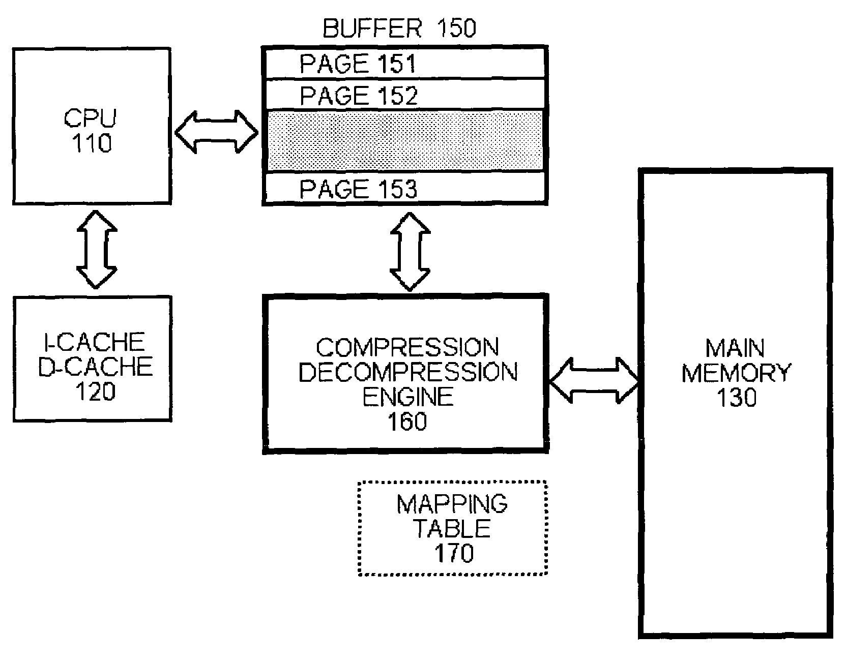
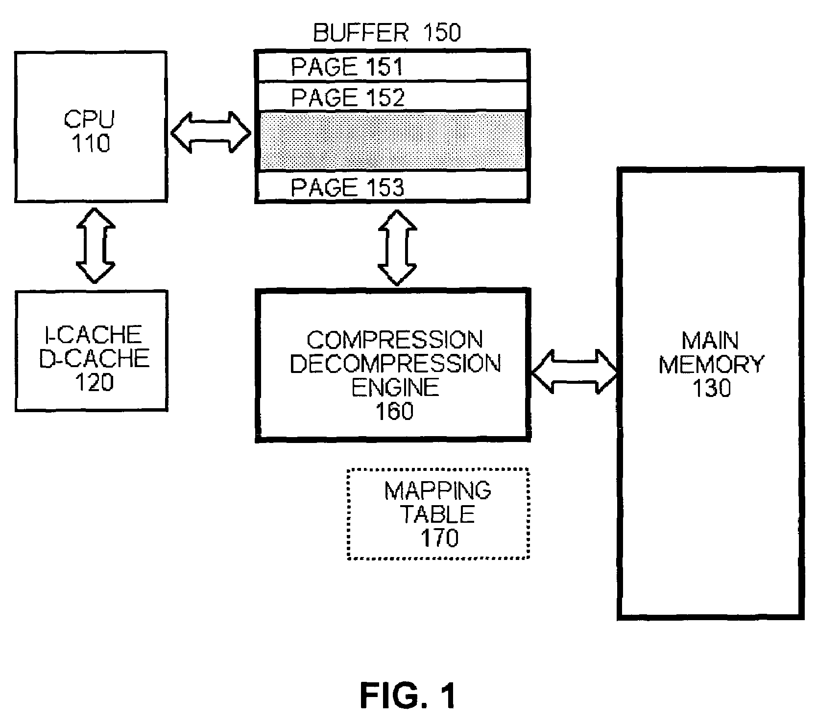
[0014]FIG. 1 is a diagram illustrating the various levels of memory hierarchy that can be used in a system built in accordance with an embodiment of an aspect of the invention. A central processing unit (CPU) 110 is shown in FIG. 1 which may or may not have one or more levels of caching 120. The cache(s) 120 can be an instruction and / or data cache. It should be noted that the memory compression architecture disclosed herein is advantageously independent of the particular CPU and caching hierarchy utilized. This approach does not require or assume any level of caching and can be readily implemented in a system without any cache. It is assumed for illustration that the system does not provide for virtual memory.

[0015]Existing architectures with multiple levels of memory hierarchy have typically been designed with a focus on performance. Given the significant performance overhead in compressing data in addition to code, it is generally beneficial to compress and decompress at levels of...


PUM


Abstract

An embedded systems architecture is disclosed which can flexibly handle compression of both instruction code and data.

Description

RELATED APPLICATIONS[0001]The present application is related to co-pending commonly-assigned U.S. utility patent applications “DYNAMIC CONTENT-AWARE MEMORY COMPRESSION AND ENCRYPTION ARCHITECTURE,” Ser. No. 10 / 869,984, and “MEMORY ENCRYPTION ARCHITECTURE,” Ser. No. 10,869,983, both filed contemporaneously with the present application on Jun. 16, 2004 and both of which are incorporated by reference herein.BACKGROUND OF THE INVENTION[0002]The present invention is related to memory architectures and, more particularly, to architectures for compression of memory in embedded systems.[0003]Compression techniques are well-known. A recent development has been to use compression techniques to reduce the size of main memory in a computer architecture. See, e.g., M. Kjelso et al., “Main Memory Hardware Data Compression,” 22nd Euromicro Conference, pages 423-30, IEEE Computer Society Press (September 1996). For example, researchers at IBM have developed the “MXT” architecture for servers which ...

Claims


Application Information

Patent Timeline
Patent Type & Authority Patents(United States)
IPC IPC(8): G06F12/00
CPCG06F12/0802H03M7/30G06F2212/401
Inventor LEKATSAS, HARISHENKEL, JOERGCHAKRADHAR, SRIMATJAKKULA, VENKATA
Owner NEC CORP
Why Eureka
Try Eureka