
Method of recognizing signal mis-wiring of a three-phase circuit

a three-phase circuit and signal recognition technology, applied in emergency protective arrangements for limiting excess voltage/current, relays, instruments, etc., can solve problems such as costly service calls, control may even shut down the system unnecessarily, and likely calculate incorrect power consumption and power factor values

Active Publication Date: 2008-07-10
TRANE INT INC
View PDF9 Cites 12 Cited by
  • Summary
  • Abstract
  • Description
  • Claims
  • Application Information

AI Technical Summary

Benefits of technology

[0016]One or more of these and/or other objects of the invention are provided by a three-phase power monitoring system that determines whether its own signal wiring is properly wired based upon (1) an observed pattern of zero crossing slope values of the three line-to-line voltages of the three-ph...

Problems solved by technology

Otherwise, if one or more signal wires are inverted, the control will likely calculate incorrect values for the power consumption and power factor.
In some cases, the control might even shut the system down unnecessarily.
When such problems occur, identifying the source of the problem or even recognizing the problem exists can be difficult and can result in costly service calls.
Moreover, once the signal wiring is identified as causing the problem, it can be difficult to determine exactly which signal wires are wired incorrectly.

Method used


Image

  • Method of recognizing signal mis-wiring of a three-phase circuit
  • Method of recognizing signal mis-wiring of a three-phase circuit
  • Method of recognizing signal mis-wiring of a three-phase circuit

Examples


Embodiment Construction

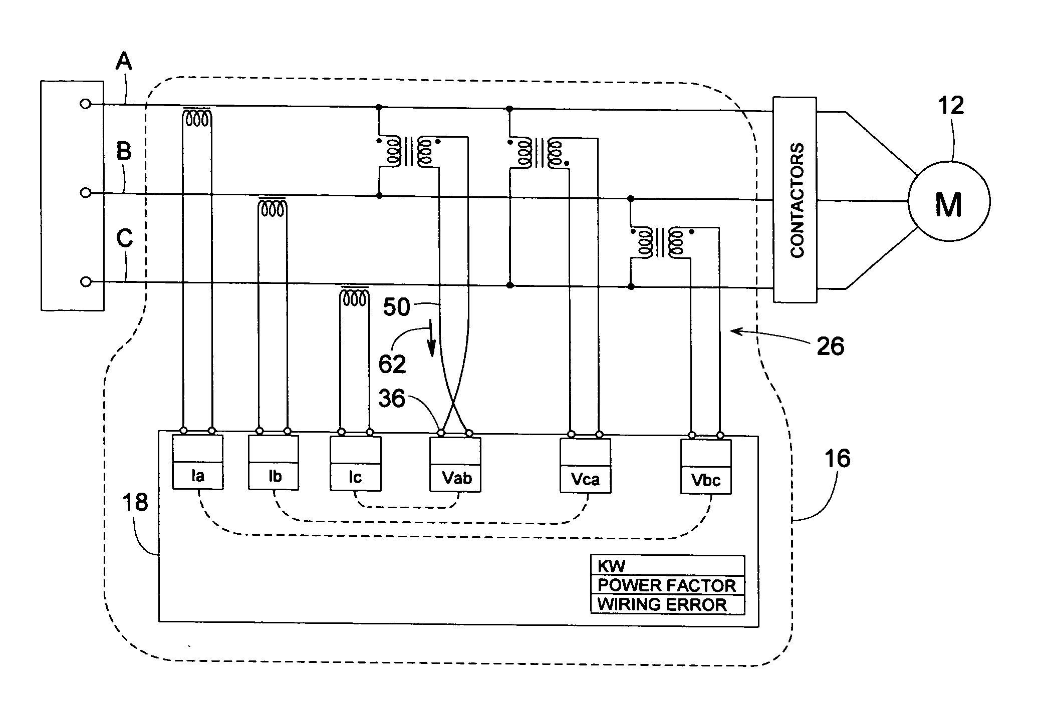
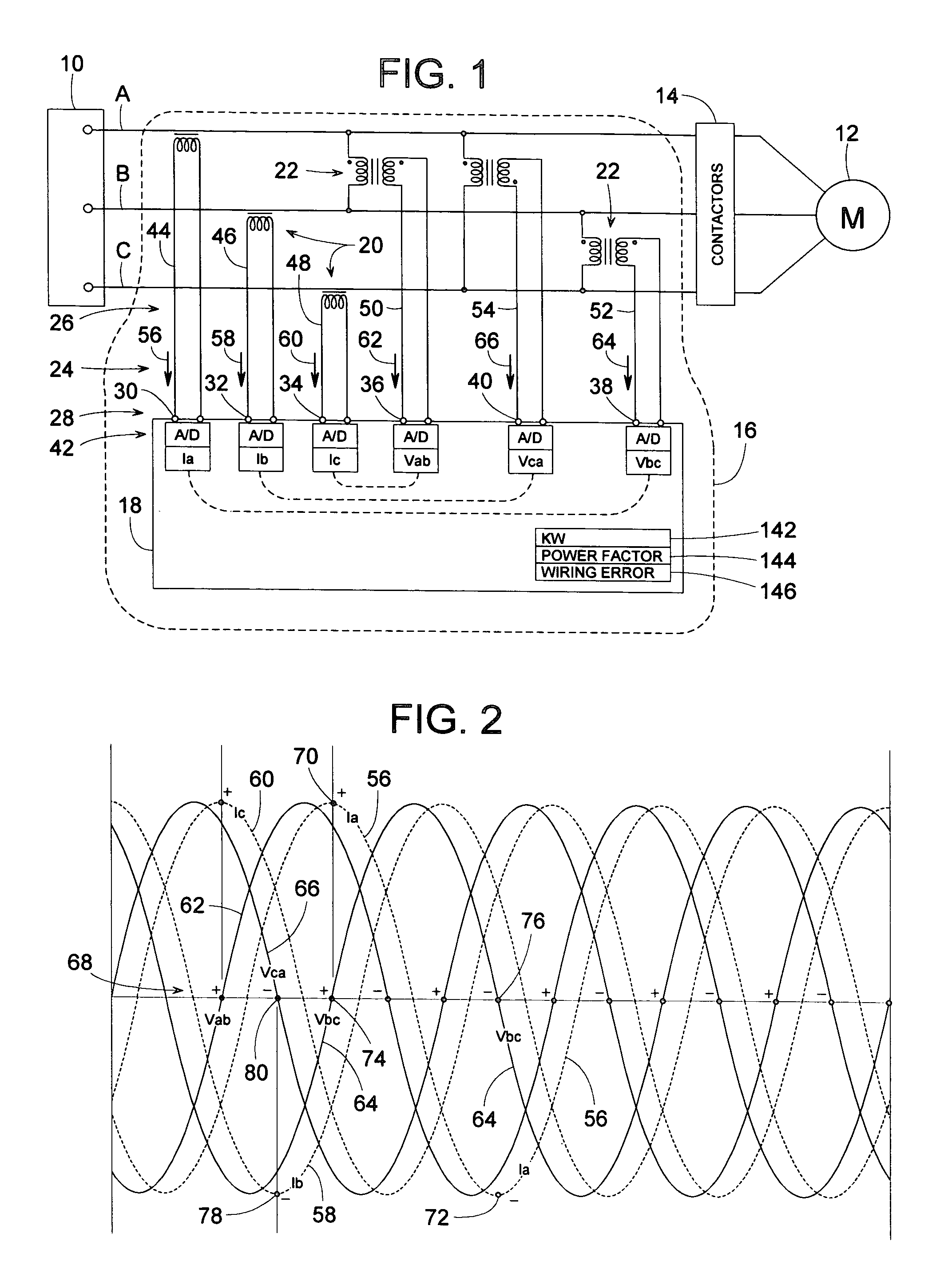
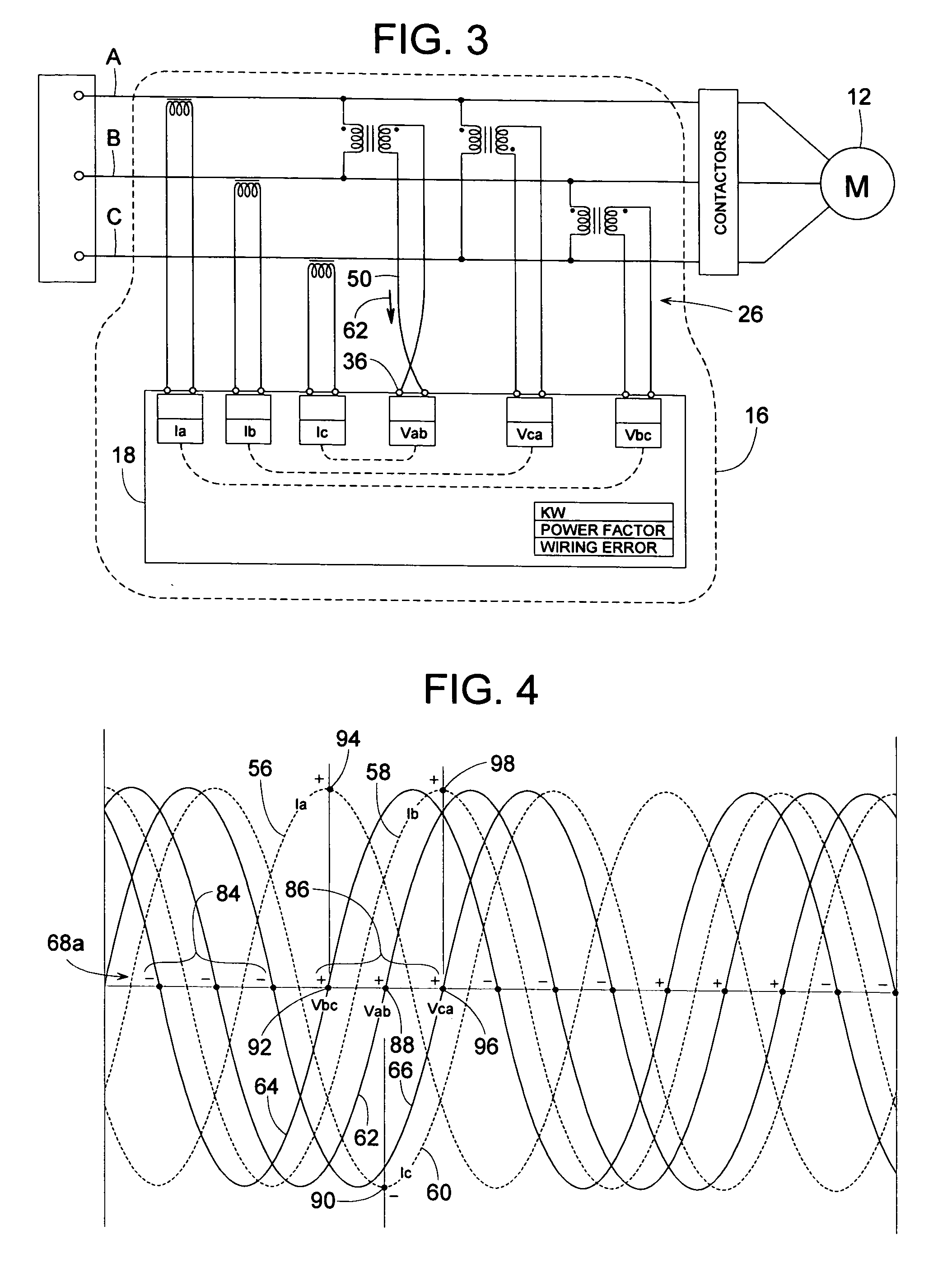
[0026]FIG. 1 shows a plurality of electrical power lines (power lines A, B and C) conveying electrical power from a three-phase power supply 10, through a set of contactors 14 (e.g. conventional motor contactors), and onto an electrical load 12 (e.g., an electric motor). To calculate the electrical load's three-phase power consumption and related power factor, an electrical system 16 with a monitoring mechanism 18 (such as a microprocessor-based circuit 18, a single logic circuit, a programmable logic module, or equivalent thereof) monitors the voltage and current of power lines A, B and C. The monitoring mechanism is described herein in connection with the microprocessor based circuit 18 but also contemplates the equivalents thereto. Microprocessor-based circuit 18 is schematically illustrated to represent any circuit that can execute a desired programmed algorithm suitable for the subject invention. Examples of microprocessor-based circuit 18 include, but are not limited to, a com...


PUM


Abstract

A signal analyzer for calculating the power consumption and power factor of a three-phase power system driving a motor includes logic that determines whether the analyzer's own input terminals are wired in a proper or inverted manner. To do this, the signal analyzer observes a pattern of zero crossing slope values of the three line-to-line voltages of the three-phase power system and observes a pattern of zero crossing slope values of the current in the three power lines. The analyzer also compares the slope of a voltage signal as the signal passes through zero volts and the sign of a corresponding current signal that exists as the voltage signal crosses zero volts. Based on the observed voltage and current patterns and the voltage-to-current relationships, the analyzer can positively identify which of a plurality of inputs or signal wires are inverted.

Description

BACKGROUND OF THE INVENTION[0001]1. Field of the Invention[0002]The subject invention generally pertains to signal wiring used in monitoring a three-phase electrical power system. The invention more specifically applies to a method for determining whether the signal wiring is properly connected to the power system.[0003]2. Description of Related Art[0004]There are many available systems for determining whether a three-phase electrical power supply is properly connected to its load. The invention, however, actually pertains to the proper wiring of signal wires, not the proper wiring of the power lines.[0005]Once a three-phase power supply is properly wired to its load, a control circuit can monitor the line voltage and current of all three phases to determine the system's power consumption and power factor. Six pairs of signal wires (three for the voltage readings and three for the current) can be used to couple the control circuit to the power lines. It is important for the signal w...

Claims


Application Information

Patent Timeline
IPC IPC(8): G01R31/08
CPCG01R31/041G01R29/18G01R31/67
Inventor MURRY, MICHAEL W.SHEPECK, MATTHEW A.JUSTIN, DENNIS L.
Owner TRANE INT INC
Learn More