Reservoir Simulation

a technology of reservoir simulation and simulation model, which is applied in the field of reserve simulation, can solve the problems of insufficient or insufficient well equations, inability to know which if any of the well equations is adequate, and insufficient computer speed or big enough to meet the ever-escalating needs of reservoir simulation, so as to improve the prediction of reservoir saturation, improve the prediction of reservoir pressure, and improve the effect of reservoir saturation

Inactive Publication Date: 2008-07-10
HALES HUGH
View PDF0 Cites 75 Cited by
  • Summary
  • Abstract
  • Description
  • Claims
  • Application Information

AI Technical Summary

Benefits of technology

[0062]In the method described in Section III, also know as the Bundy method, the use of any of the previous methods in combination with streamline simulation and dynamic griding vastly improve the prediction of reservoir saturations in modern simulation.
[0063]In addition to the use of Weber equations to improve the prediction of reservoir pressures, another improvement to the field is described herewith. In Section III, an exemplary implementation of a reservoir simulator is described that combines certain simulation technologies herein described to create a simulator of increased speed, accuracy, and versatility. These new technologies include:

Problems solved by technology

The fact that traditional, Taylor-series based, finite difference equations are inaccurate at representing reservoir pressures near the wells in petroleum reservoirs has long been known.
However, none of the proposed well equations are adequate for all wells, and the growing complexity of well geometries, including horizontal wells, slant wells, and multilateral completions, makes it difficult to know which if any of the well equations is adequate.
However, despite the enormous increases in computer speeds and memories that have occurred over the years, computers have never been fast enough or big enough to meet the ever-escalating needs of reservoir simulation.
Differences usually result from inaccurate data, but sometimes they occur as the result of mathematical shortcuts.
However, the problem of matching by adjusting thousands of data values, using simulators that take hours to run, remains a very difficult task.6
It is never possible to have enough data to accurately describe the reservoir.
Even for relatively shallow reservoirs, it is impractical to have wells drilled sufficiently close to one another that well logs can accurately determine all the variations in properties throughout the reservoir.
However, the cost is many simulations, one for each geostatistical model.
However, this emerging technology too, requires many simulations and hence is dependent on fast simulators.

Method used


Image

  • Reservoir Simulation
  • Reservoir Simulation
  • Reservoir Simulation

Examples


Embodiment Construction

Section I. Method of Formulating Finite Difference Equations

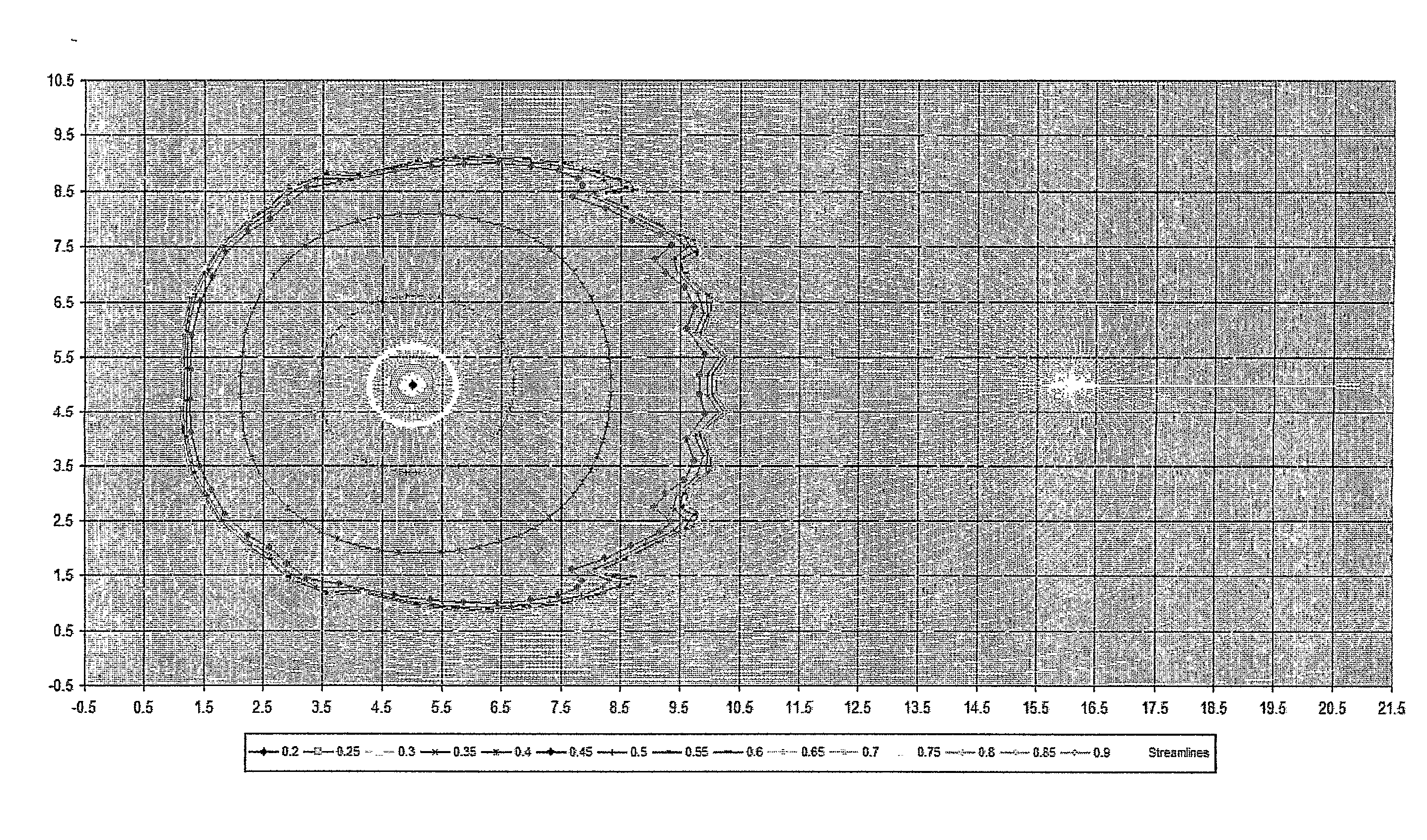
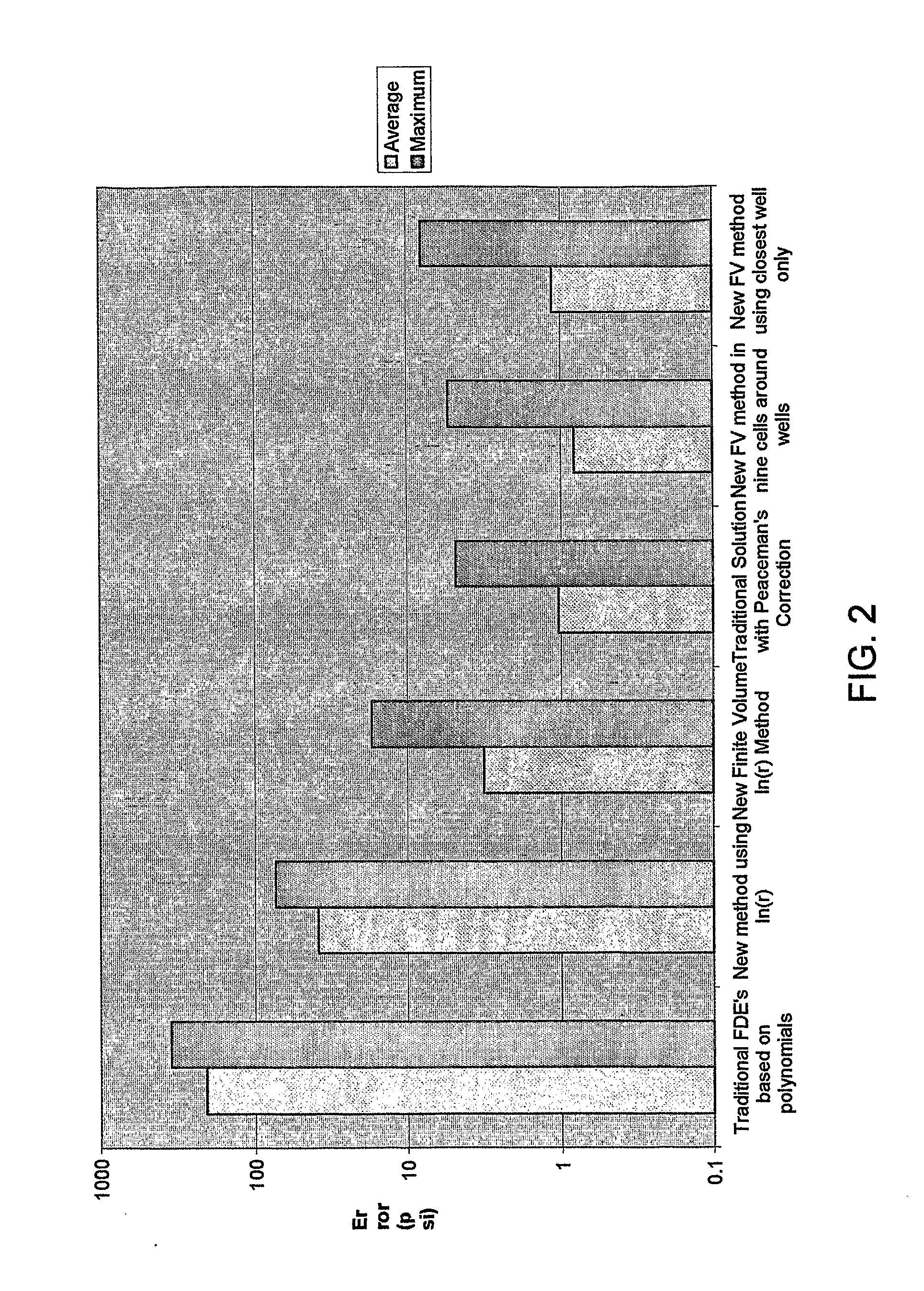
[0094]An aspect of the present invention involves the use of finite difference equations that incorporate the singularities in pressure at the wells. The Weber finite difference equations accurately represent the actual pressures at the wellbore and elsewhere in the well cells. No well equations are required. The Weber method hypothesizes that traditional finite difference equations are unable to predict wellbore pressures because they are based on Taylor series, which are polynomial in form. Polynomials are continuous functions and are unable to represent singularities. Instead of polynomials, finite difference equations are derived on 1) ln(r)-functions and 2) 1 / r functions, both of which are singular as r approaches zero.

[0095]Finite Difference Equations Based on Logarithmic Functions

[0096]In an infinite, homogeneous reservoir with steady-state flow, the flow velocity, q, from an infinite straight line source in the rese...


PUM

PropertyMeasurementUnit
pressuresaaaaaaaaaa
permeabilityaaaaaaaaaa
porosityaaaaaaaaaa

Abstract

Disclosed are methods for simulating pressures and saturations of oil, gas, and water in an oil reservoir with production and injection wells, which include (1) using of new approximating linear algebraic (finite difference) equations that more accurately represent actual pressures by basing the equations on new functional forms: ln(r) or 1/r, (2) solve the set equations using by defining a coarse grid array and a fine grid array nested in the fine grid array, and solving the coarse grid array and using the resulting solution to fix points in the fine grid array before it is solved, and (3) defining and solving a dynamic grid array based upon constant saturation contours.

Description

CROSS REFERENCE TO RELATED APPLICATIONS[0001]This application claims priority from U.S. Provisional Patent Application 60 / 577,975, filed Jun. 7, 2004.BACKGROUND OF INVENTION[0002]The fact that traditional, Taylor-series based, finite difference equations are inaccurate at representing reservoir pressures near the wells in petroleum reservoirs has long been known. Most simulators do not simulate wellbore pressures directly with finite difference equations, but instead correct simulated well cell pressures to obtain the actual wellbore pressures with a “well equation”. Many use an empirical productivity index, PI:9Q=PI·(pwell−pcell)  (I-1)In 1978, Peaceman1 was perhaps the first to suggest a method of calculating the PI, or the difference in the well bore and well cell pressures:PI=2πKhμ[ln(0.2Δxrw)]-1orpwell-pcell=12πQμKhln(0.2Δxrw)(I-2)[0003]This expression is based on the pressures in a 2-D, homogeneous, isotropic, reservoir with vertical, fully penetrating wells arranged in a five...

Claims


Application Information

Patent Timeline
Patent Type & Authority Applications(United States)
IPC IPC(8): G06G7/50G01N33/28
CPCG01N33/28E21B43/00
Inventor HALES, HUGHWEBER, DANIELHARDY, BENBUNDY, BRADBAXTER, LARRY
Owner HALES HUGH
Why Eureka
Try Eureka