

Motor
a motor and motor technology, applied in the direction of motor/generator/converter stopper, dynamo-electric converter control, motor/generator/converter stopper, etc., can solve the problems of inability to arbitrarily select, high torque and high-speed rotation (high power) cannot be achieved, and achieve high torque and high torque. , the effect of facilitating the flow of driving currents
- Summary
- Abstract
- Description
- Claims
- Application Information
AI Technical Summary
Benefits of technology
Problems solved by technology
Method used
Image

Examples
first embodiment
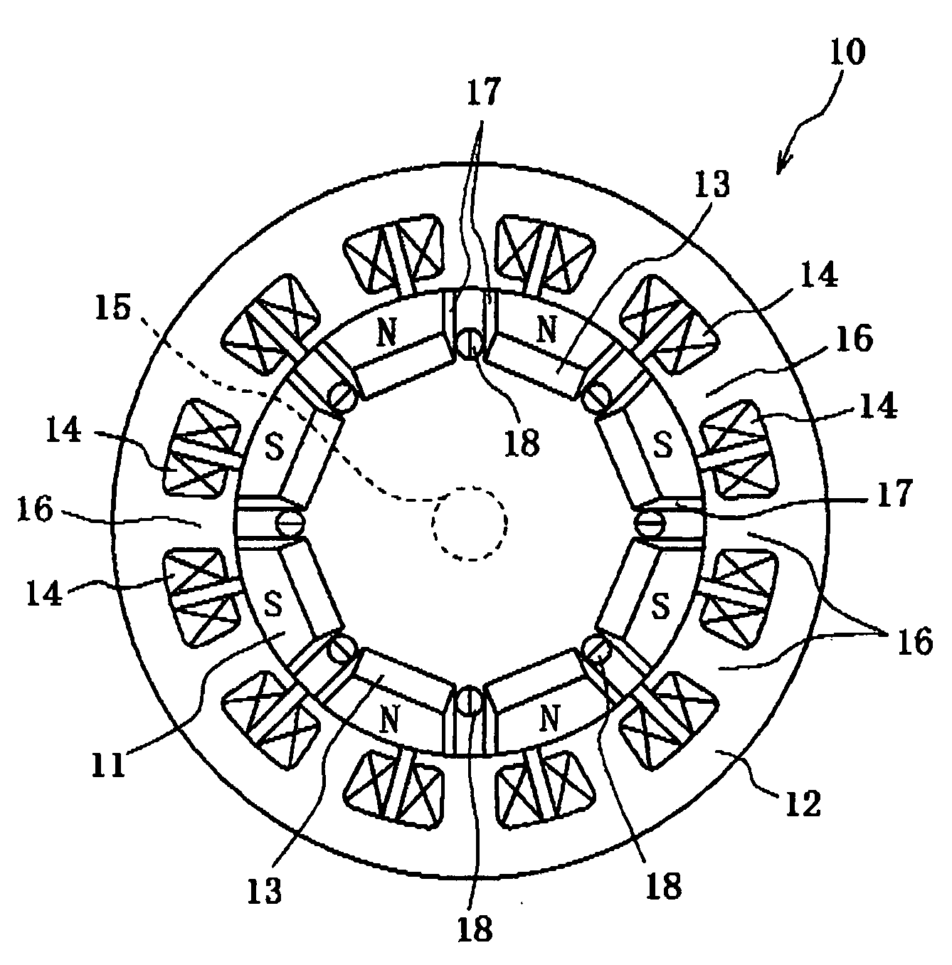
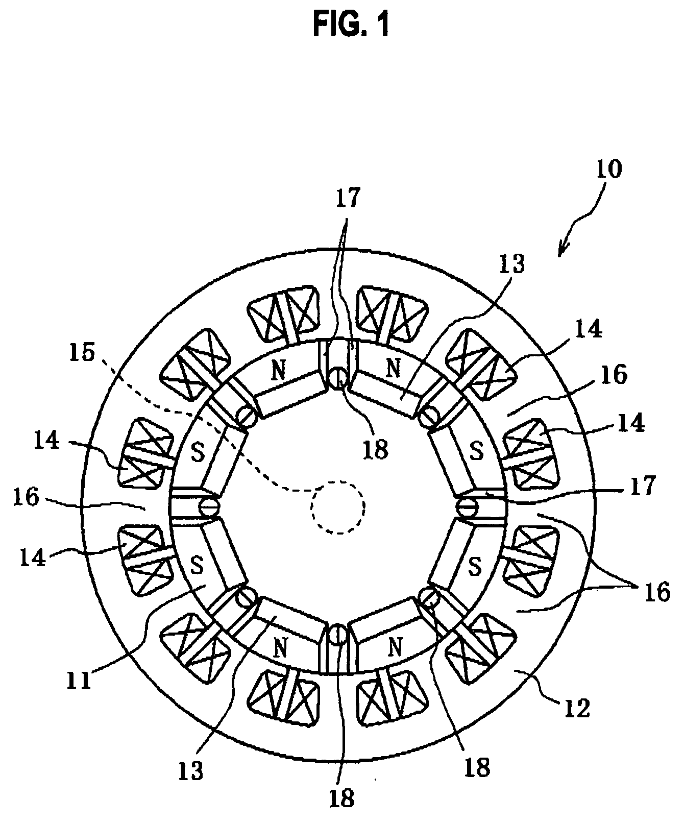
[0030]FIG. 1 is a radial cross-sectional view showing a stator and a rotor in a motor according to a first embodiment of the present invention. As shown in FIG. 1, a motor 10 includes a rotor 11 and a stator 12. The rotor 11 has magnets (permanent magnets) 13, and the stator 12 has field coils 14. The rotor 11 has a rotating shaft 15 disposed perpendicularly to a surface of the rotor 11, and the rotating shaft 15 is rotatably held by a case (not shown).
[0031]The stator 12 is formed into a cylindrical shape by stacking circular ferromagnetic steel plates along a central axis direction of the rotating shaft 15. On an inner circumferential side of the stator 12, a plurality of slots 16 for winding the coils 14 which generate a rotating magnetic field are disposed approximately equally spaced apart from each other in an inner circumferential direction so as to protrude toward the rotating shaft 15.
[0032]The rotor 11 rotatably attached to the stator 12 is similarly formed into a cylindri...
second embodiment
[0038]FIG. 3 shows a rotor according to a second embodiment of the present invention. FIG. 3(a) shows forward salient-pole characteristics obtained by magnetic path switching parts, and FIG. 3(b) shows inverse salient-pole characteristics obtained by the magnetic path switching parts. As shown in FIG. 3, in this rotor 20, a magnetic path is switched by use of a magnetic path switching part 21 rotatably provided along a plane of the rotor 20 on the inner side of the respective magnets 13 in a radial direction of the rotor 20. Both air gaps 17 provided parallel to each other between the magnets 13 of the same pole are extended to an outer circumferential edge of the magnetic path switching part 21 so as to correspond to the magnetic path switching part 21. Other configurations and operations are the same as those of the rotor 11 in the first embodiment.
[0039]The magnetic path switching part 21 has a shape like a rotor of an SR (Switched Reluctance) motor, for example. Moreover, the ma...
third embodiment
[0042]FIG. 4 shows a rotor according to a third embodiment of the present invention. As shown in FIG. 4, in a rotor 25, a plurality of magnetic elements 26 are provided between adjacent air gaps 17 and, instead of the magnetic path switching part 21, air gaps 27 and a plurality of magnetic elements 28 disposed in the air gaps 27 are provided. Other configurations and operations are the same as those of the rotor 20 in the second embodiment.
[0043]FIG. 5 shows configurations of each of the magnetic elements in FIG. 4. FIG. 5(a) shows a configuration when a voltage is applied, and FIG. 5(b) shows a configuration when no voltage is applied. As shown in FIG. 5, each of the magnetic elements 26 and each of the magnetic elements 28 have the same configuration, and the magnetic element 26 (28) has a magnetostrictor 26a (28a) and two piezoelectric elements 26b (28b) sandwiching the magnetostrictor 26a (28a.) therebetween.
[0044]When a voltage is applied to the piezoelectric elements 26b (28b)...
PUM
 Abstract
Description
Claims
Application Information