Measurement method, exposure method, exposure apparatus, and device fabrication method
a measurement method and exposure technology, applied in measurement devices, instruments, printing, etc., can solve the problems of deterioration of aerial images, distortion (scan distortion), and insufficient to achieve a high-resolution exposure apparatus, so as to accurately measure any synchronization error
- Summary
- Abstract
- Description
- Claims
- Application Information
AI Technical Summary
Benefits of technology
Problems solved by technology
Method used
Image

Examples
first embodiment
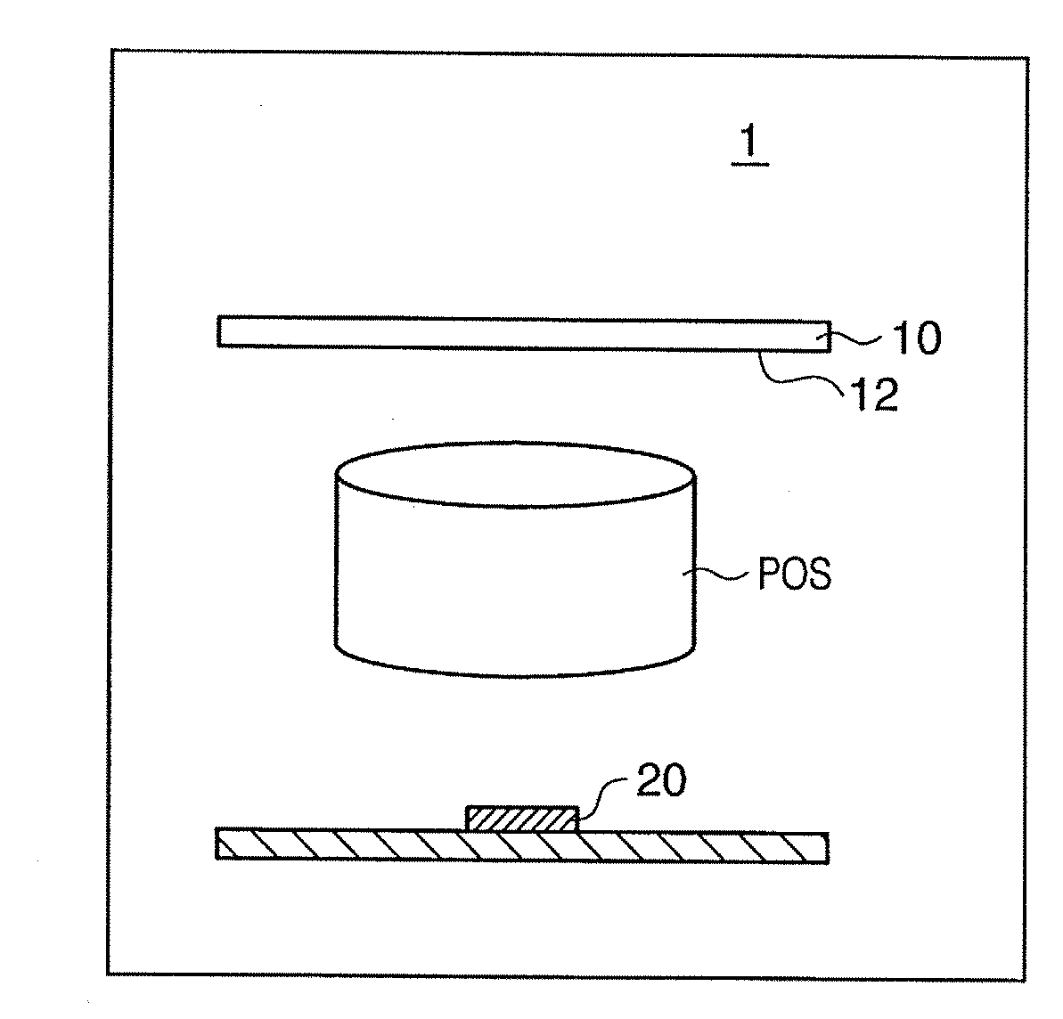
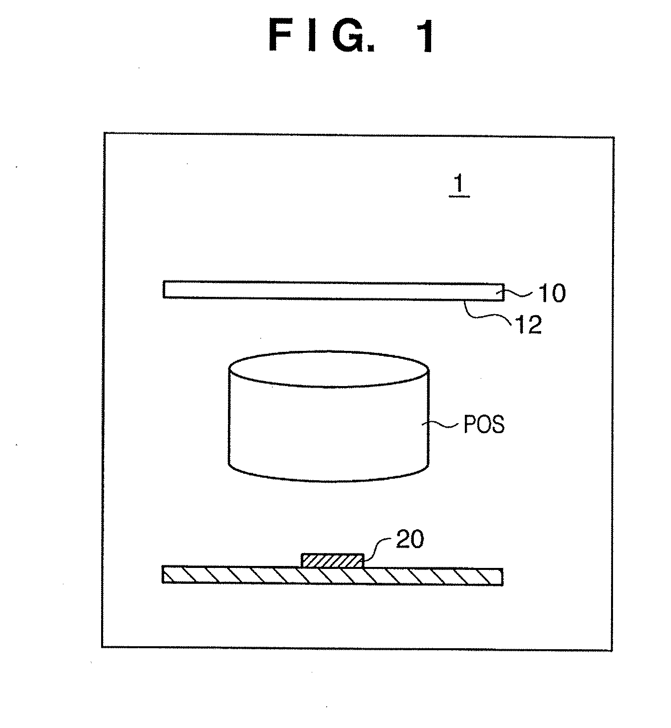
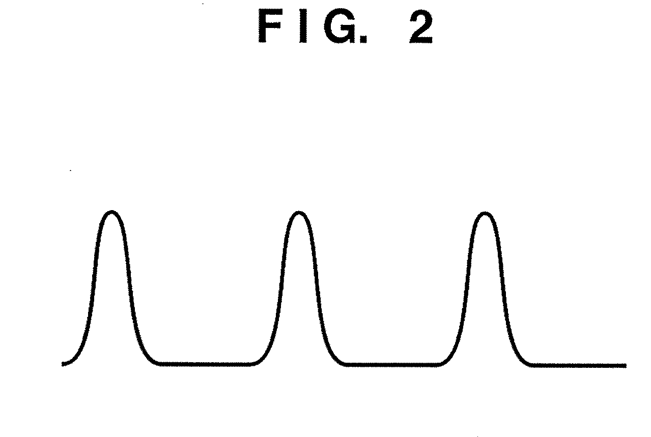
[0047]In the first embodiment, an L&S pattern (periodic pattern) is used as a measurement pattern 12 of a measurement mask 10. The measurement pattern 12 of the measurement mask 10 is an L&S pattern (periodic pattern) with a period p and forms a light intensity distribution (aerial image) AI1 with the period p, as shown in FIGS. 4A and 4B. Two measurement units 20 are arranged for the light intensity distribution AI1 formed by the measurement pattern 12. The measurement units 20 each include a light-shielding board SB having openings 22 with the period p formed as minute slits, and a light intensity sensor 24 which includes a photodetector and is arranged under the openings 22. The two measurement units 20 will be referred to as a first measurement unit 20A and second measurement unit 20B hereinafter. Note that FIG. 4A is a chart showing the positional relationship between a light intensity distribution formed by the measurement pattern 12 of the measurement mask 10 and an opening 2...
second embodiment
[0076]In the second embodiment, a contact hole pattern is used as a measurement pattern 12 of a measurement mask 10. The contact hole pattern is two-dimensionally formed on the measurement mask 10. An axis parallel to the mask surface is defined as the x-axis, an axis perpendicular to the x-axis and parallel to the mask surface is defined as the y-axis, and an axis perpendicular to the mask surface is defined as the z-axis. The period of the contact hole pattern in the x direction may be different from that in the y direction, and its center need not always be located on an intersection in an orthogonal grid pattern. However, the second embodiment assumes that the period of a contact hole pattern in the x direction is equal to that in the y direction, and its center is located on an intersection in an orthogonal grid pattern.
[0077]The measurement pattern (contact hole pattern) 12 of the measurement mask 10 in the second embodiment forms a light intensity distribution (aerial image) ...
PUM
 Abstract
Description
Claims
Application Information
 - R&D
- Intellectual Property
- Life Sciences
- Materials
- Tech Scout
- Unparalleled Data Quality
- Higher Quality Content
- 60% Fewer Hallucinations
Browse by: Latest US Patents, China's latest patents, Technical Efficacy Thesaurus, Application Domain, Technology Topic, Popular Technical Reports.
© 2025 PatSnap. All rights reserved.Legal|Privacy policy|Modern Slavery Act Transparency Statement|Sitemap|About US| Contact US: help@patsnap.com