Micro x-ray source

Inactive Publication Date: 2008-07-17
TECH UNIV DELFT
View PDF9 Cites 30 Cited by
  • Summary
  • Abstract
  • Description
  • Claims
  • Application Information

AI Technical Summary

Benefits of technology

[0015]Making only the spot area thinner, provides a very concentrated region where the X-rays are generated. This effectively restricts the divergence of these X-rays and thus improves the resolution that can be attained wi

Problems solved by technology

However, this is disadvantageous, as apart from the intended X-rays emitted by the target such a substrate pro

Method used


Image

  • Micro x-ray source
  • Micro x-ray source

Examples


Embodiment Construction

[0024]The invention is further illustrated by the following non-limiting example.

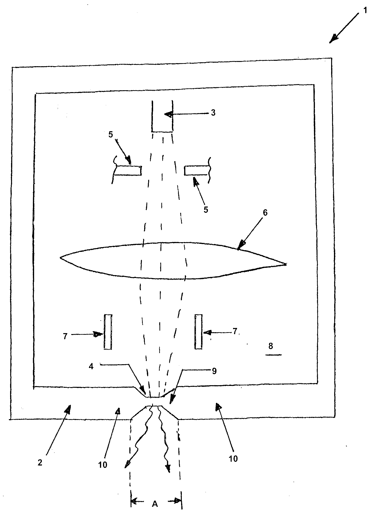
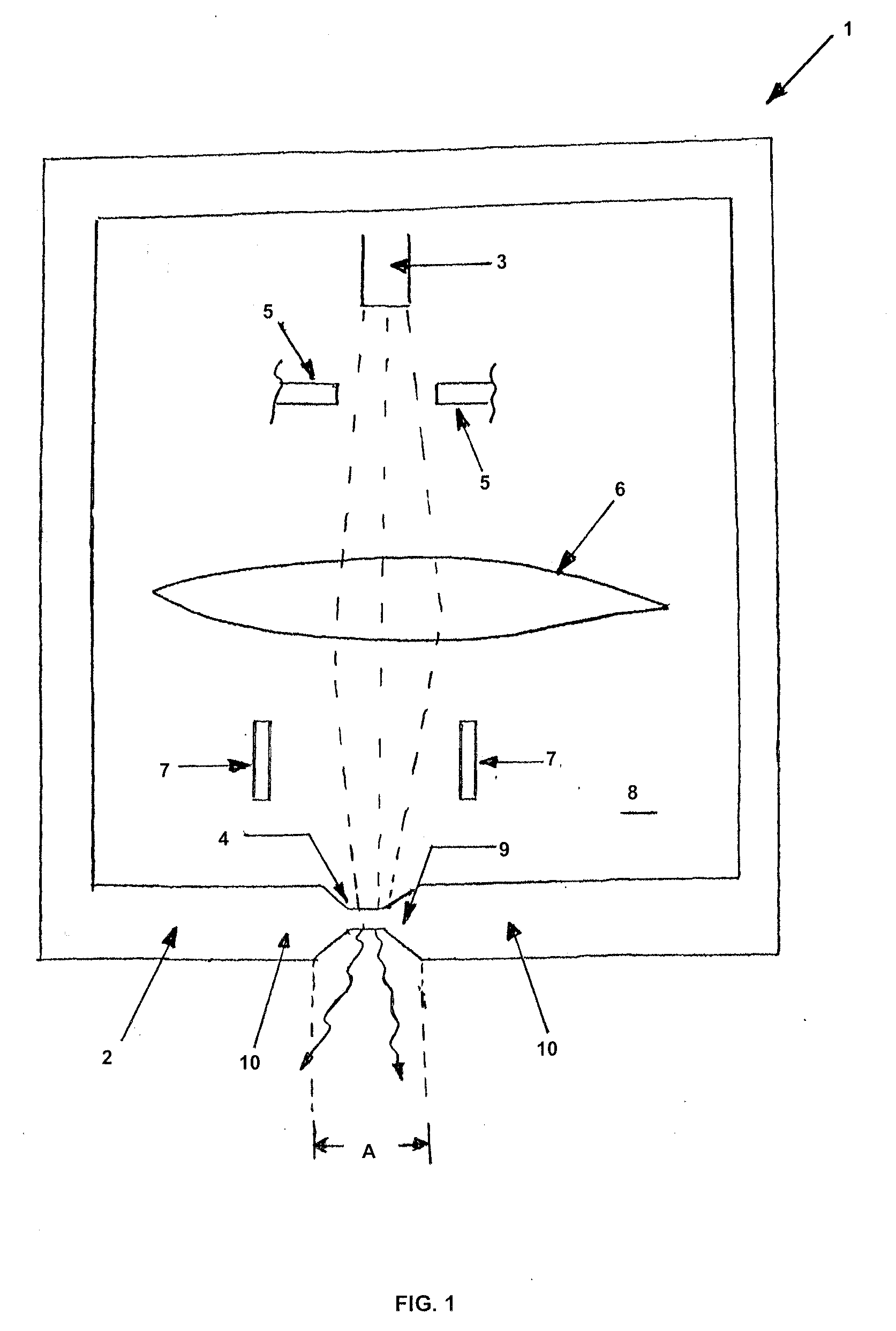
[0025]The micro X-ray source 1 shown in the FIG. 1 comprises a target acting as anode 2, as well as a cathode 3 interacting during operation with the target 2 and functioning as electron source.

[0026]The target 2 is embodied in the form of a metal foil. A suitable material is, for example, tungsten, iridium or osmium.

[0027]The target 2 further possesses a spot 4 where the electrons from the electron source 3 collide with the material of the target 2.

[0028]The FIGURE further shows that in the direction of the electron beam directed at the target 2, the micro X-ray source 1 may be provided with an extractor 5, a lens 6 and deflector plates 7. The person skilled in the art is acquainted with the function and working of these components and a further explanation is not needed.

[0029]The FIGURE clearly shows that the metal foil of the target 2 is locally thinner at the spot 4.

[0030]The person skilled in the a...


PUM


Abstract

A micro X-ray source comprising a target acting as anode, and a cathode, which during operation interacts with the target and functions as electron source, wherein the target is embodied as a metal foil possessing a spot where the electrons from the electron source arrive, and the metal foil being locally thinner at the spot.

Description

CROSS-REFERENCE TO RELATED APPLICATIONS[0001]This application is a continuation-in-part application of Patent Cooperation Treaty Patent Application Serial No. PCT / NL2006 / 000118, entitled “Micro X-Ray Source”, to Technische Universiteit Delft from Pieter Kruit, Cornelis W. Hagen and Elvira H. Mulder, filed on Mar. 8, 2006, and the specification and claims thereof are incorporated herein by reference.[0002]This application claims priority to and the benefit of the filing of Netherlands Patent Application Serial No. 1028481, entitled “Microröntgenbron” (Micro X-Ray Source), filed on Mar. 8, 2005, and the specification and claims thereof are incorporated herein by reference.STATEMENT REGARDING FEDERALLY SPONSORED RESEARCH OR DEVELOPMENT[0003]Not Applicable.INCORPORATION BY REFERENCE OF MATERIAL SUBMITTED ON A COMPACT DISC[0004]Not Applicable.[0005]COPYRIGHTED MATERIAL[0006]Not Applicable.BACKGROUND OF THE INVENTION[0007]1. Field of the Invention (Technical Field)[0008]The present invent...

Claims


Application Information

Patent Timeline
IPC IPC(8): H01J35/12H01J9/18
CPCH01J35/14H01J2235/186H01J2235/087H01J35/18H01J35/116H01J35/186H01J35/12
Inventor KRUIT, PIETERHAGEN, CORNELIS WOUTERMULDER, ELVIRA HENDRIKA
Owner TECH UNIV DELFT
Why Eureka
Try Eureka