Eureka AIR delivers breakthrough ideas for toughest innovation challenges, trusted by R&D personnel around the world.

Negative electrode for nonaqueous electrolyte secondary battery, its manufacturing method, and nonaqueous electrolyte secondary battery using the same

a technology of nonaqueous electrolyte and secondary batteries, which is applied in the direction of electrode manufacturing processes, electrochemical generators, cell components, etc., can solve the problems of reducing the capacity, increasing the volume of elements, peeling, etc., and achieves the effect of suppressing the change in the shape of column members, easy manufacturing of highly reliable negative electrodes, and maintaining spa

Inactive Publication Date: 2008-07-17
PANASONIC CORP
View PDF3 Cites 11 Cited by
  • Summary
  • Abstract
  • Description
  • Claims
  • Application Information

AI Technical Summary

Benefits of technology

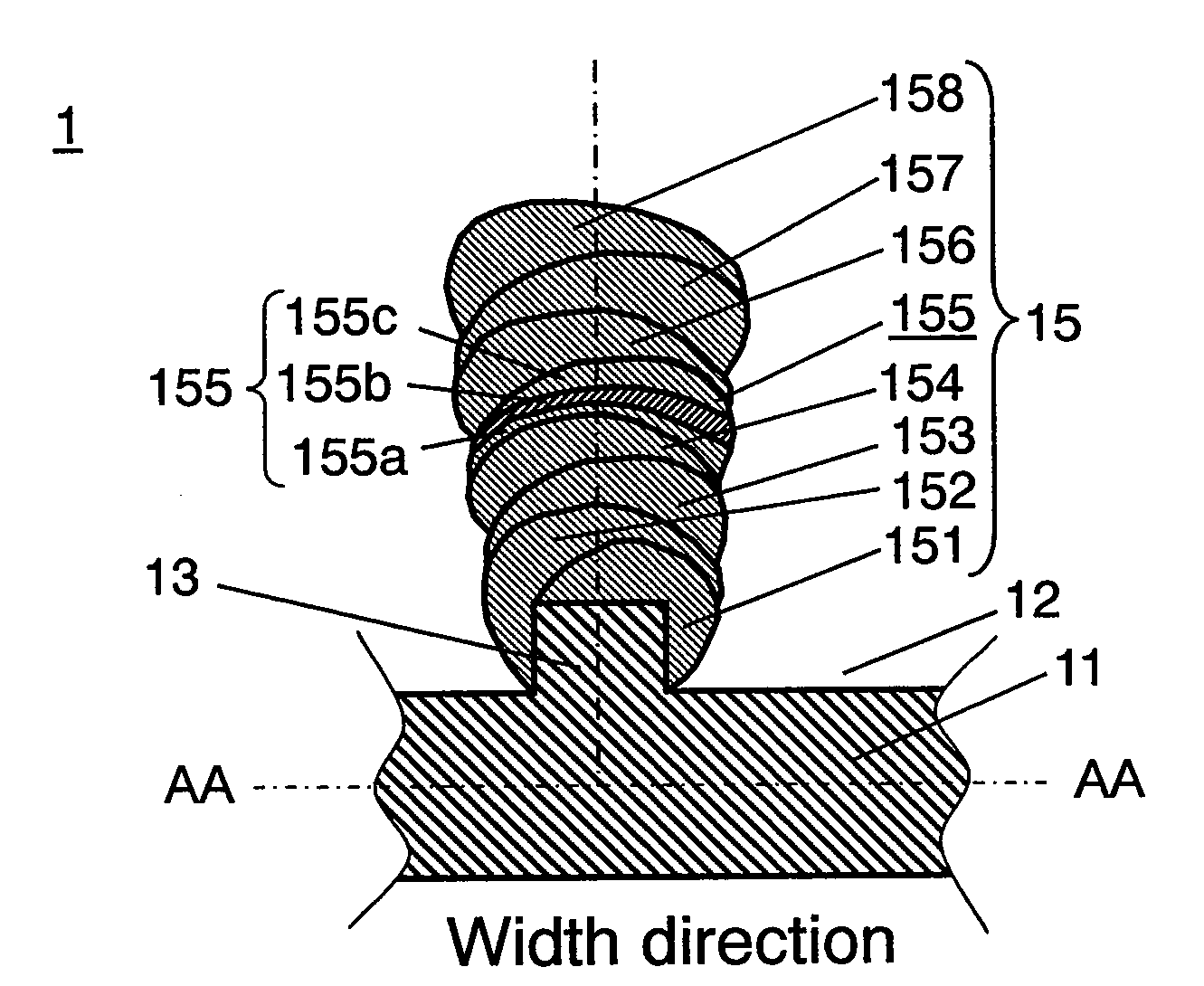
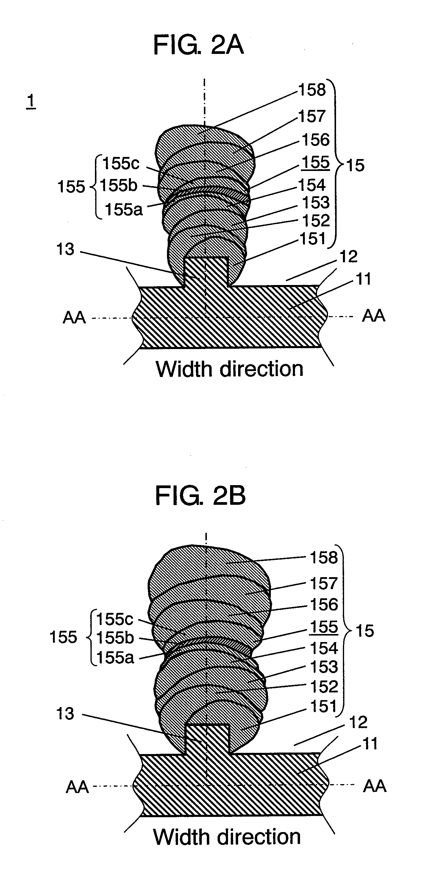
[0016]Thus, the change in shape of the column member is partially suppressed, maintaining the space between column members, and it is possible to realize a negative electrode ensuring a long lifetime and capable of greatly improving the high rate discharge and low temperature characteristics.
[0018]In this way, it is possible to maintain space between column members by partially suppressing the change in shape of column members and to easily manufacture highly reliable negative electrodes free from generation of creases on the current collector even when the theoretical capacity density of the negative electrode active material used exceeds 833 mAh / cm3.
[0019]Also, the nonaqueous electrolyte secondary battery of the present invention comprises a negative electrode for the nonaqueous electrolyte secondary battery, a positive electrode capable of inserting and extracting lithium ion in a reversible fashion, and nonaqueous electrolyte. Accordingly, it is possible to manufacture a nonaqueous electrolyte secondary battery which may assure excellent safety and reliability.

Problems solved by technology

However, these elements increase in volume when inserting lithium ion during the time of charging.
Accordingly, when negative electrode active material is formed by depositing thin film of the element on a current collector by using CVD method or sputtering method in particular, the expansion and contraction of the negative electrode active material takes place due to insertion and extraction of lithium ion, and there is a possibility that peeling occurs due to worsening of tight contact between the negative electrode active material and negative electrode current collector during repetition of the charging / discharging cycle.
However, since the negative electrode active material is shrinking at start of charging, the metal surface of the current collector is sometimes exposed via the space.
As a result, the exposed current collector confronts the positive electrode at the time of charging, and it gives rise to deposition of lithium metal, causing worsening of the safety and lowering of the capacity.
Accordingly, it has been unable to realize the prevention of peeling of the negative electrode active material from the current collector and the generation of creases and the enhancement of capacity at the same time.
Further, because the electrolyte is shut up in space between columnar negative electrode active materials expanded and contacted on each other, the movement of lithium ion at the initial stage of discharge is prevented, and there arises a problem of discharge characteristics such as high rate discharge or under low temperatures conditions.
For example, in the case of negative electrode active material formed of SiOx, when the value of x is very small, the expansion and contraction are great, and therefore, peeling is liable to take place due to the stress especially in case of forming on the interface of the current collector.
Consequently, as the charge / discharge cycle goes on, the negative electrode active material is liable to peel off from the convex of current collector surfaces due to the stress, resulting in lowering of the reliability.
Also, the electrolyte is shut up in space 555 between columnar negative electrode active materials expanded and contacted on each other, and therefore, the movement of lithium ion at the initial stage of discharge is prevented, and there arises a problem of discharge characteristics such as high rate discharge or under low temperatures conditions.

Method used


Image

  • Negative electrode for nonaqueous electrolyte secondary battery, its manufacturing method, and nonaqueous electrolyte secondary battery using the same
  • Negative electrode for nonaqueous electrolyte secondary battery, its manufacturing method, and nonaqueous electrolyte secondary battery using the same
  • Negative electrode for nonaqueous electrolyte secondary battery, its manufacturing method, and nonaqueous electrolyte secondary battery using the same

Examples


first exemplary embodiment

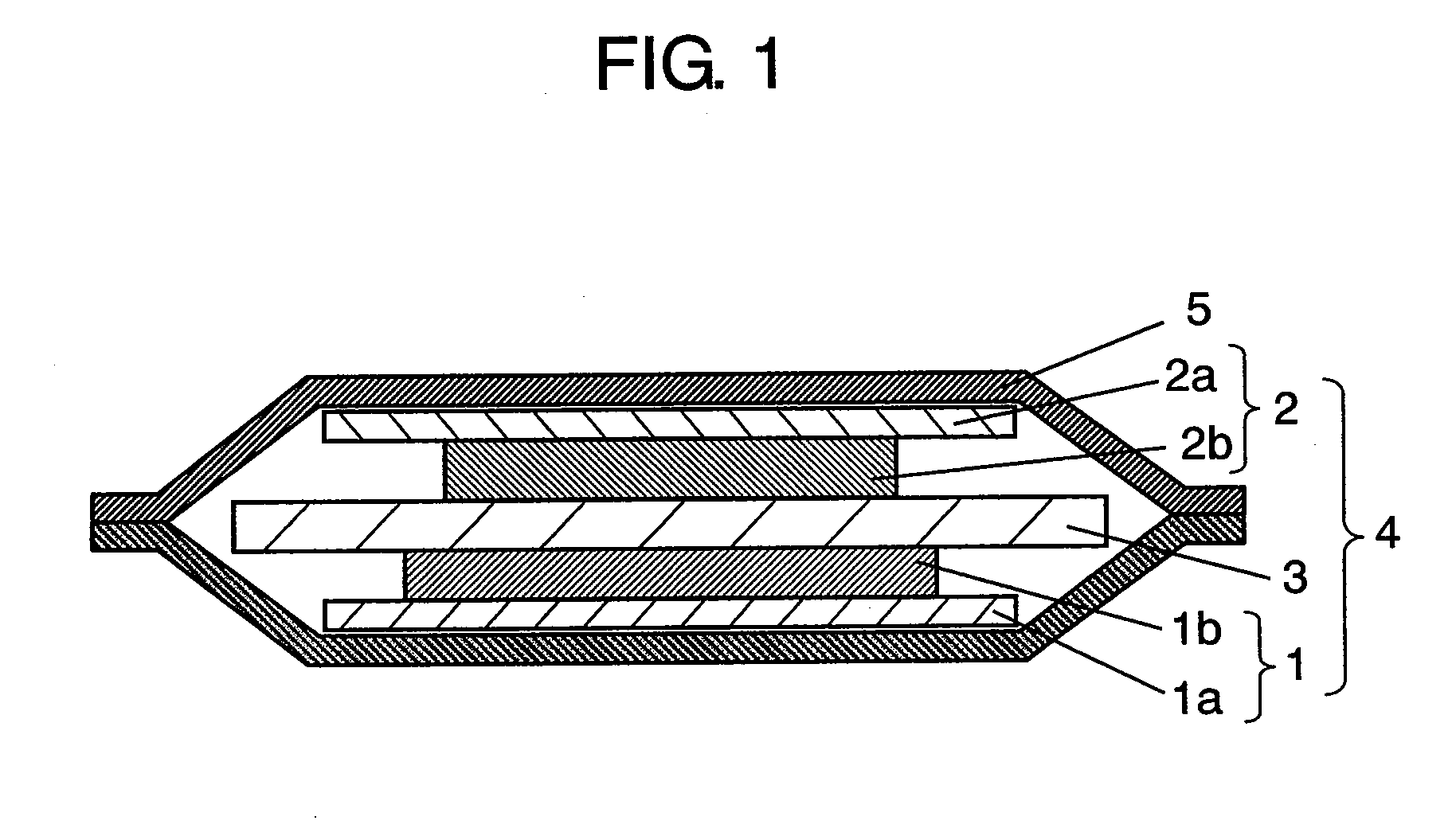
[0054]FIG. 1 is a sectional view of a nonaqueous electrolyte second battery in the first exemplary embodiment of the present invention.

[0055]As shown in FIG. 1, the laminate type nonaqueous electrolyte secondary battery (hereinafter referred to as battery) is provided, as described in detail later, with negative electrode 1, positive electrode 2 for reduction of lithium ion during discharge, which is opposed to negative electrode 1, and electrode group 4 formed of porous separator 3 disposed therebetween to prevent negative electrode 1 and positive electrode 2 from coming into direct contact with each other. Electrode group 4 and nonaqueous electrolyte (not shown) having lithium ion conductivity are housed in outer case 5. The nonaqueous electrolyte having lithium ion conductivity is contained in separator 3. Also, positive electrode current collector 2a and negative electrode current collector 1a are connected with one end of positive electrode lead (not shown) and negative lead (n...

second exemplary embodiment

[0154]The structure of a negative electrode in the second exemplary embodiment of the present invention will be described in the following by using FIG. 10A to FIG. 10C.

[0155]FIG. 10A is a partially sectional schematic view showing the structure of the negative electrode in the second exemplary embodiment of the present invention. FIG. 10B is a schematic view for describing the change in value x in the width direction of active material of each columnar portion in the second exemplary embodiment of the present invention. FIG. 10C is a schematic view for describing the change in value x in the height direction of active material of each columnar portion in the second exemplary embodiment of the present invention. In this exemplary embodiment, a laminate type battery the same as shown in FIG. 1 is used, and the detailed description is omitted. Also, the component materials for the positive electrode mixture layer, positive electrode current collector, current collector, and columnar p...

third exemplary embodiment

[0241]The structure of a negative electrode in the third exemplary embodiment of the present invention will be described in the following with reference to FIG. 16A to FIG. 16C.

[0242]FIG. 16A is a partially sectional schematic view showing the structure of the negative electrode in the third exemplary embodiment of the present invention. FIG. 16B is a schematic view for describing the change in value x in the width direction of active material of each columnar portion in the third exemplary embodiment of the present invention. FIG. 16C is a schematic view for describing the change in value x in the height direction of active material of each columnar portion in the third exemplary embodiment of the present invention. In this exemplary embodiment, a laminate type battery the same as shown in FIG. 1 is used, and the detailed description is omitted. Also, the component materials for the positive electrode mixture layer, positive electrode current collector, current collector, and colum...


PUM

PropertyMeasurementUnit
oblique angle θ2aaaaaaaaaa
widthaaaaaaaaaa
widthaaaaaaaaaa

Abstract

A negative electrode for nonaqueous electrolyte secondary battery comprising a current collector with a concave and a convex formed at least on one surface thereof, and a column member having n (n≧2) stages of laminated columnar portions obliquely formed on the convex of the current collector, wherein a layer being less in expansion and contraction due to insertion and extraction of lithium ion is disposed in the column member.

Description

BACKGROUND OF THE INVENTION[0001]1. Field of the Invention[0002]The present invention relates to a nonaqueous electrolyte secondary battery excellent in charge / discharge characteristics, and more particularly, it relates to a negative electrode for nonaqueous electrolyte secondary battery which is excellent in high rate characteristic and low temperature characteristic, its manufacturing method, and a nonaqueous electrolyte secondary battery using the same.[0003]2. Background Art[0004]A lithium ion secondary battery representing a nonaqueous electrolyte secondary battery is light-weight and very high in electromotive force and energy density. Therefore, there is an increasing demand for lithium ion secondary battery as a driving power source for various types of portable electronic equipment such as portable telephone, digital camera, video camera, and notebook personal computer, and mobile communication equipment.[0005]A lithium ion secondary battery comprises a positive electrode ...

Claims


Application Information

Patent Timeline
Patent Type & Authority Applications(United States)
IPC IPC(8): H01M4/48H01M4/04H01M4/131H01M4/1391H01M4/1395H01M4/58H01M10/052H01M10/36
CPCH01M4/0423H01M4/131H01M4/1391H01M4/1395H01M4/38H01M4/483Y10T29/49115H01M4/621H01M4/765H01M4/78H01M10/052Y02E60/122H01M4/5825H01M4/386Y02E60/10
Inventor UGAJI, MASAYAHASEGAWA, MASAKIKASHIWAGI, KATSUMI
Owner PANASONIC CORP
Why Eureka
Eureka Blog
Learn More