Villari torque sensor excitation and pickup arrangement for magnetrostrictive shafts

a magnetrostrictive shaft and torque sensor technology, applied in the direction of instruments, work measurement, measurement devices, etc., can solve the problems of cost and complexity, measurement more sensitive to circumferential inhomogeneities, and the fabrication of sensing coils onto discrete poles of sensors becomes very difficult for small shaft diameters, etc., to achieve tighter requirements on axial play, cost and complexity, and cost

Inactive Publication Date: 2008-07-24
DELPHI TECH INC
View PDF24 Cites 16 Cited by
  • Summary
  • Abstract
  • Description
  • Claims
  • Application Information

AI Technical Summary

Benefits of technology

[0006]Fabrication of the sensing coils onto discrete poles of the sensor becomes very difficult for small shaft diameters. Multiple Four-Branch Sensors have been proposed to sense the inductance changes on a larger portion of the shaft circumference simultaneously. See Fleming SAE Paper 890482. However, this multiplies the number of discrete coils (five coils required per four branch section) and hence cost and complexity, especially for small diameter shafts. Sensors with cylindrical excitation and sensing coils are described in W. J. Fleming, “Computer-Model Simulation Results for Three Magnetostrictive Torque Sensor Designs,” SAE Paper 910857 (March 1991). However, these do not function with shafts having a cylindrically uniform distribution of magnetostrictive material because the flux is no longer forced to follow the principal axes. A chevron pattern must be added to the magnetostrictive shaft material to force the flux to flow along the principal axes. This has a number of disadvantages including, stress risers along the cuts that impact durability, tighter requirements on the axial play of the shaft (the chevrons must be precisely aligned with the sensor poles) and added manufacturing steps and costs.

Problems solved by technology

A disadvantage of this arrangement is that it senses inductance changes within only a portion of the shaft circumference making the measurements more sensitive to circumferential inhomogeneities.
Fabrication of the sensing coils onto discrete poles of the sensor becomes very difficult for small shaft diameters.
However, this multiplies the number of discrete coils (five coils required per four branch section) and hence cost and complexity, especially for small diameter shafts.
However, these do not function with shafts having a cylindrically uniform distribution of magnetostrictive material because the flux is no longer forced to follow the principal axes.
This has a number of disadvantages including, stress risers along the cuts that impact durability, tighter requirements on the axial play of the shaft (the chevrons must be precisely aligned with the sensor poles) and added manufacturing steps and costs.

Method used


Image

  • Villari torque sensor excitation and pickup arrangement for magnetrostrictive shafts
  • Villari torque sensor excitation and pickup arrangement for magnetrostrictive shafts
  • Villari torque sensor excitation and pickup arrangement for magnetrostrictive shafts

Examples


Embodiment Construction

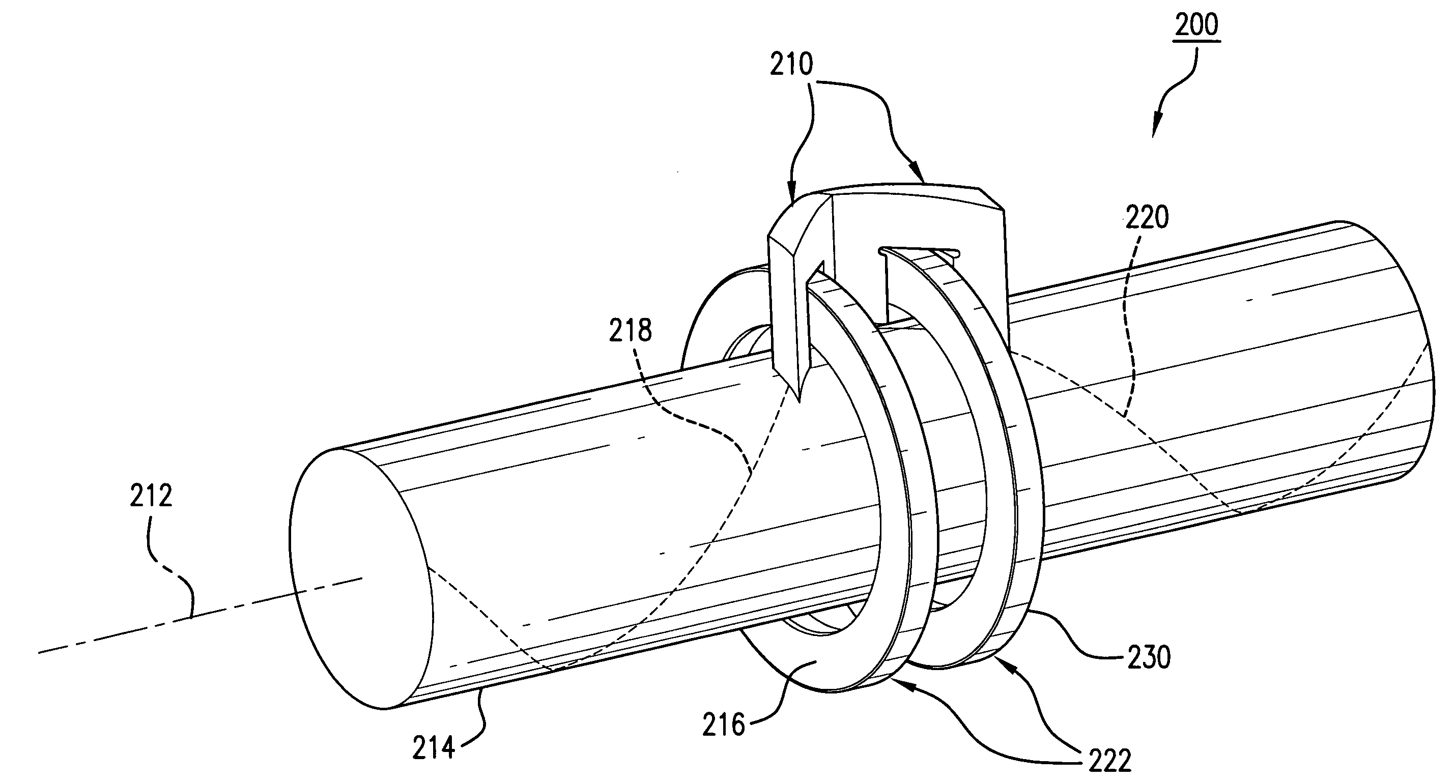
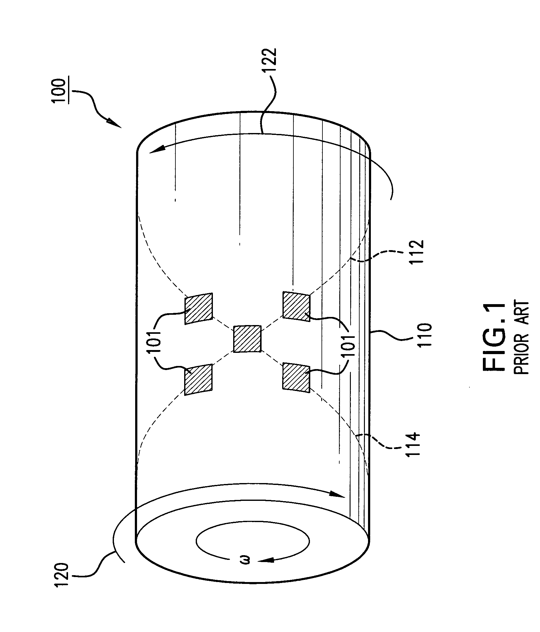
[0013]The inventions described and / or claimed herein are directed to various sensor arrangements having cylindrical excitation and sensing coils that can be used with shafts having a cylindrically uniform distribution of magnetostrictive material without any surface modifications such as chevrons, etc., that force flux along the principal axes.

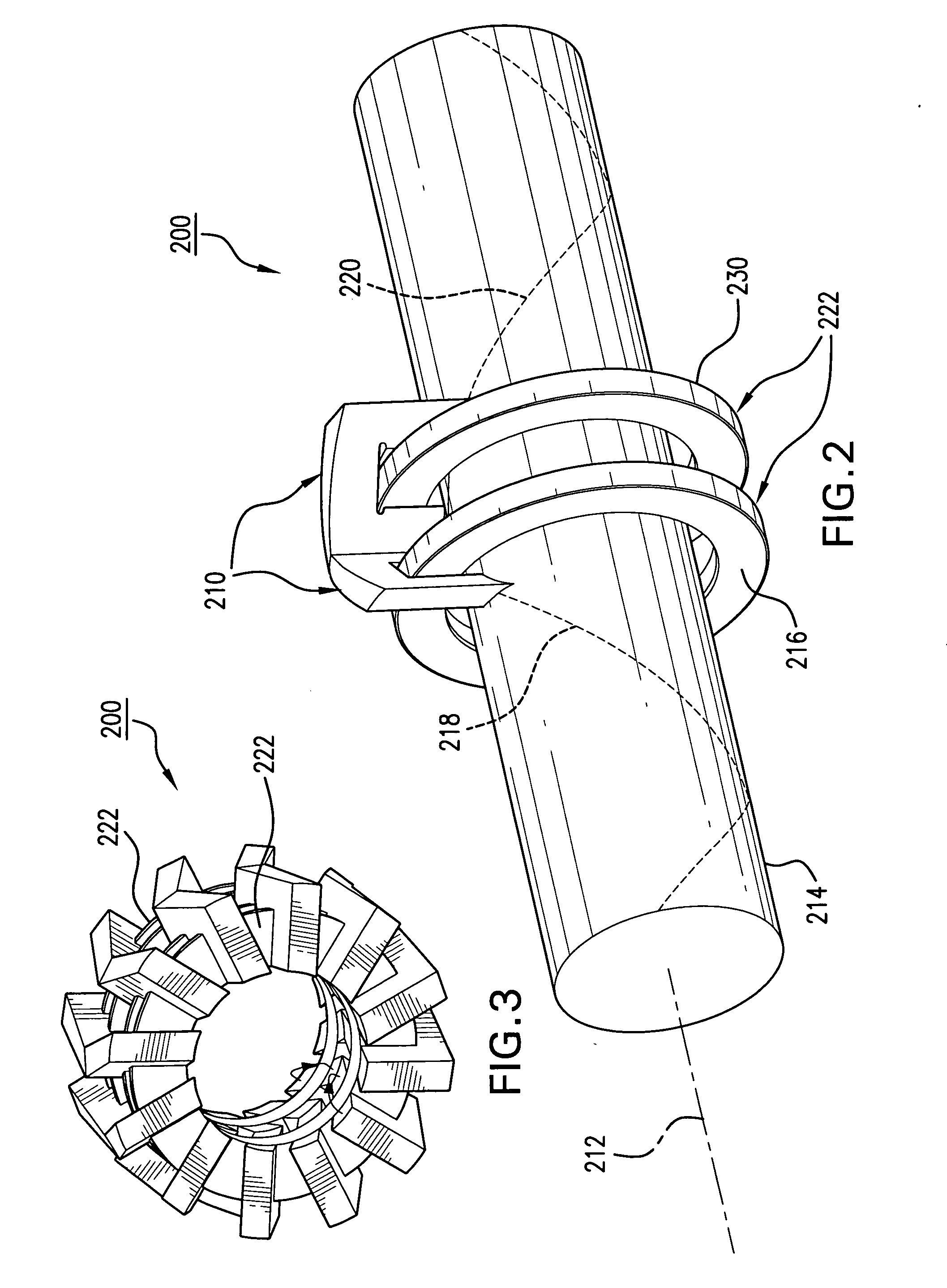
[0014]FIG. 2 is a schematic diagram of a simple sensor arrangement illustrating a concept of the inventions described and / or claimed herein. A sensor 200 includes skewed sensor pole pieces 210 that straddle cylindrical coil bobbins 222. The sensor has a unique pole structure that forces flux along the principal axes. Discrete pole pieces 210 are skewed with respect to a shaft axis 212 of a shaft 214 and that straddle concentric excitation coils 216 and sensing coils 230, the excitation coils 216 and sensing coils 230 being wound on coil bobbins 222. Each bobbin contains one excitation coil and one sensing coil. One set of poles is aligned with...


PUM

PropertyMeasurementUnit
frequencyaaaaaaaaaa
frequencyaaaaaaaaaa
frequencyaaaaaaaaaa

Abstract

A torque sensor based on the Villari effect. The sensor uses high frequency alternating magnetic fields and the Villari effect to determine the state of stress / strain inside a magnetostrictive shaft for the purpose of measuring torque. The invention teaches design elements for the sensor and shaft; namely, the desirable magnetic, electric and structural properties for various elements of the sensor.

Description

BACKGROUND AND SUMMARY[0001]Applying a magnetic field causes stress that changes the physical properties of a magnetostrictive material. The reverse is also true: applying stress to a magnetostrictive material changes its magnetic properties (e.g., magnetic permeability). This is called the Villari effect.[0002]The inventions described and / or claimed herein relate to novel torque sensor topologies that use high frequency alternating magnetic fields and the Villari effect to determine the state of stress / strain inside a shaft made of a magnetostrictive material for the purpose of measuring torque. The inventions relate to various design elements for the sensor and shaft including but not limited to desirable magnetic, electric and structural properties for various elements of the sensor.[0003]Various materials are known to be magnetostrictive, that is, their permeability p varies with the amount of stress applied to the material. These materials have been used in various configuratio...

Claims


Application Information

Patent Timeline
Patent Type & Authority Applications(United States)
IPC IPC(8): G01L3/10
CPCG01L3/105G01L3/102
Inventor NEHL, THOMAS W.VAN STEENKISTE, THOMAS H.SMITH, JOHN R.
Owner DELPHI TECH INC
Why Eureka
Try Eureka