
Throttling Valve and Method for Enlarging Liquid Droplet Sizes in the Throttled Fluid Stream

a technology of throttling valve and liquid droplet, which is applied in the direction of diaphragm valve, engine diaphragm, separation process, etc., can solve the problems of gas quality problems, large volume of condensed liquid droplets, and large hydrocarbon droplets

Active Publication Date: 2008-07-24
TWISTER BV
View PDF11 Cites 32 Cited by
  • Summary
  • Abstract
  • Description
  • Claims
  • Application Information

AI Technical Summary

Benefits of technology

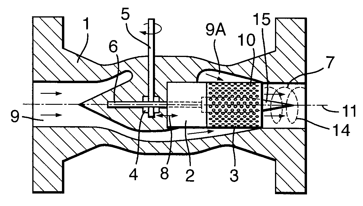
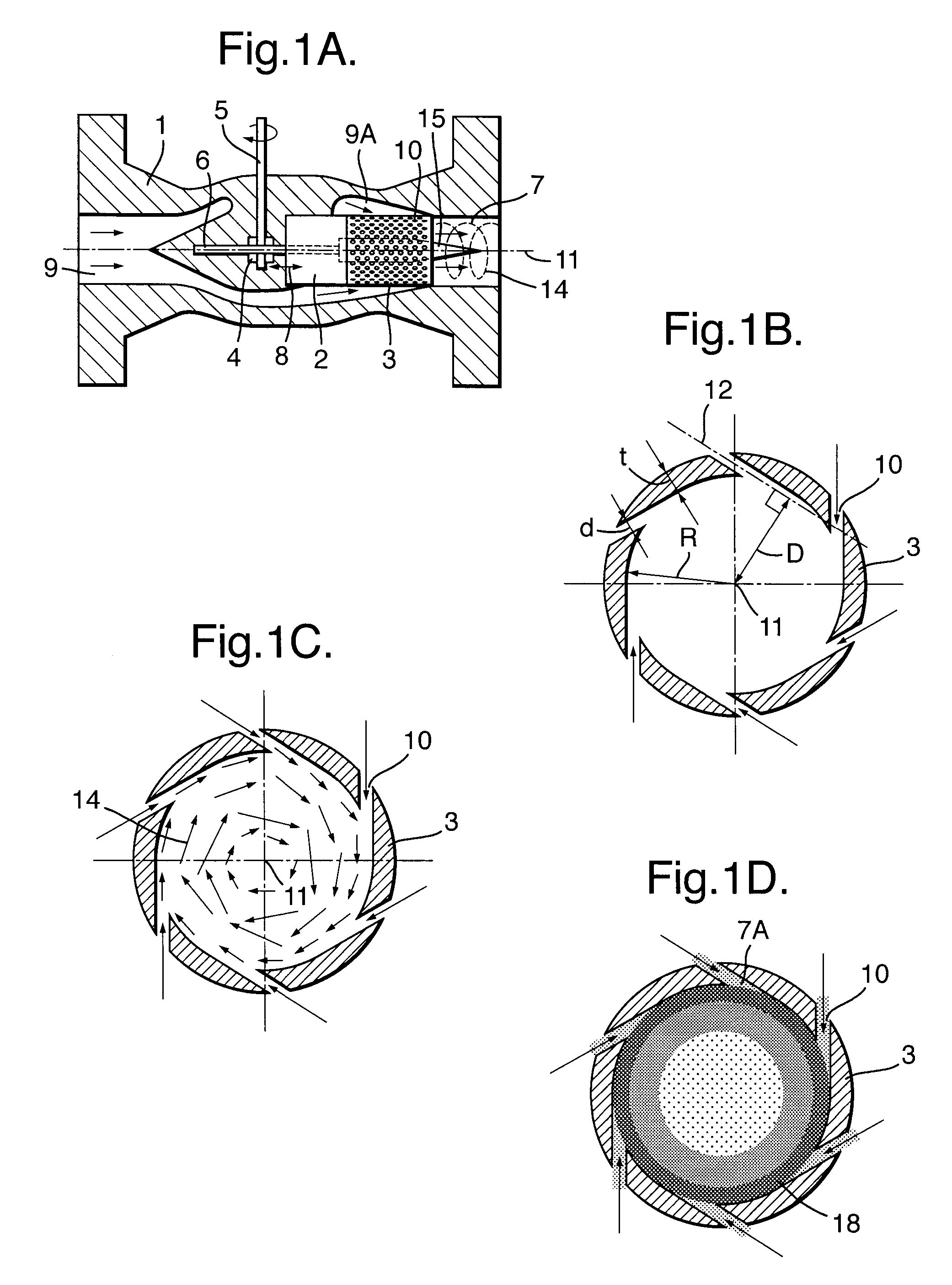
[0011]The throttling valve optionally comprises a substantially conical central body which is arranged in the fluid outlet channel and which is substantially co-axial to a central axis of the fluid outlet channel and which generates a fluid outlet channel having a gradually increasing cross-sectional area in downstream direction, thereby generating a vortex with a swirl factor that promotes growth and coalescence of condensed fluid droplets.

Problems solved by technology

From time to time gas quality problems do occur due to suboptimal separation efficiency.
In those cases it is often the hydrocarbon dew point, which remains too high, which indicates that especially hydrocarbon droplets tend to be too small.
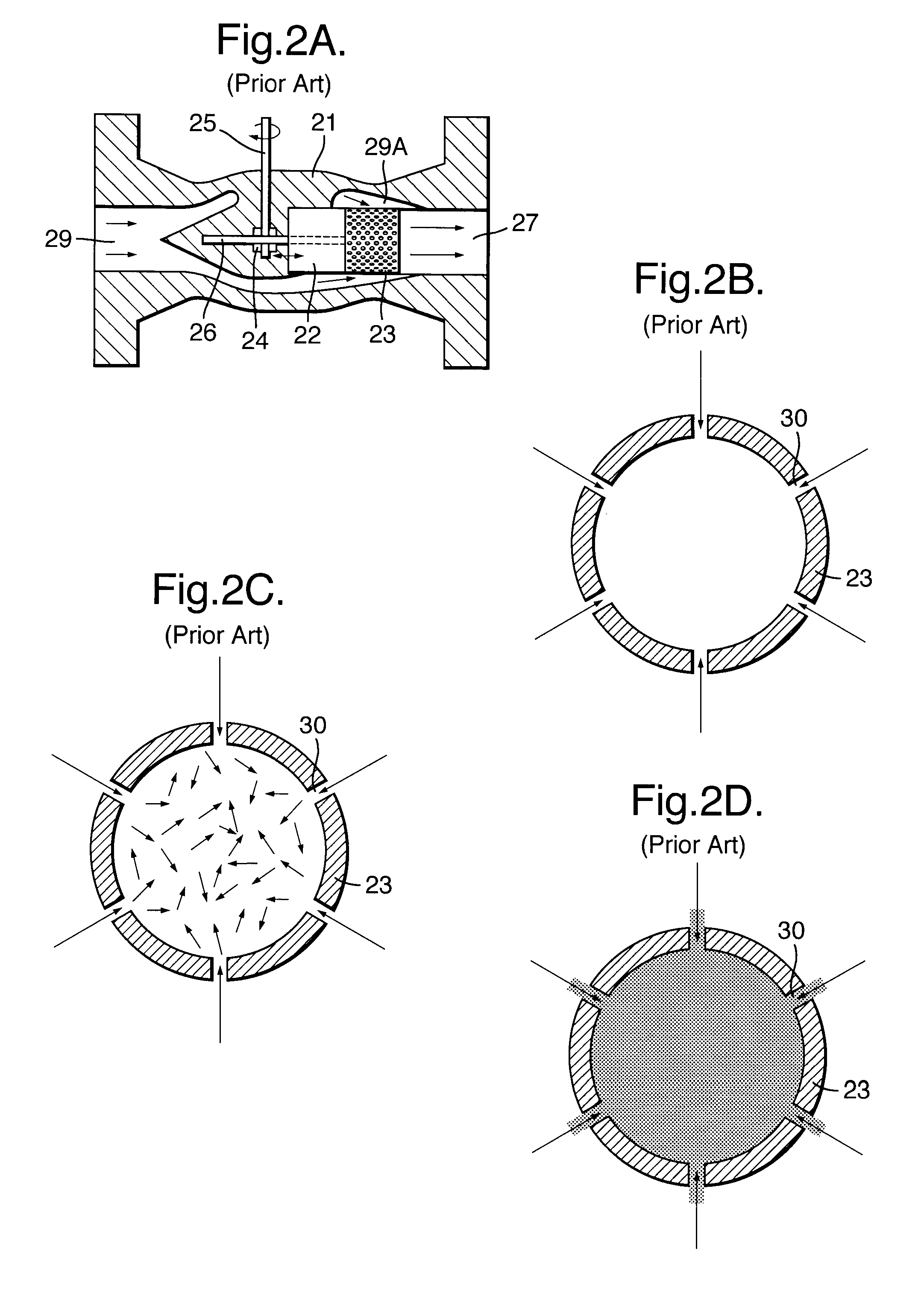
A problem with the known Joule Thomson and other throttling valves is that the size of the condensed liquid droplets is generally small, such that a mist flow is generated from which the liquid and gaseous phases cannot be easily separated.

Method used


Image

  • Throttling Valve and Method for Enlarging Liquid Droplet Sizes in the Throttled Fluid Stream
  • Throttling Valve and Method for Enlarging Liquid Droplet Sizes in the Throttled Fluid Stream
  • Throttling Valve and Method for Enlarging Liquid Droplet Sizes in the Throttled Fluid Stream

Examples


Embodiment Construction

[0026]The embodiment of the throttling valve according to present invention shown in FIG. 1A-1D has a valve geometry able to enhance the coalescence process of droplets formed during the expansion along the flow path of a Joule-Thomson or other throttling valve. These larger droplets are better separable than would be the case in traditional Joule-Thomson or other throttling valves.

[0027]The valve shown in FIG. 1A comprises a valve housing 1 in which a piston-type valve body 2 and associated perforated sleeve 3 are slideably arranged such that by rotation of a gear wheel 4 at a valve shaft 5 a teethed piston rod 6 pushes the piston type valve body up and down into a fluid outlet channel 7 as illustrated by arrow 8. The valve has an fluid inlet channel 9 which has an annular downstream section 9A that may surround the piston 2 and / or perforated sleeve 3 and the flux of fluid which is permitted to flow from the fluid inlet channel 9 into the fluid outlet channel 7 is controlled by the...


PUM

PropertyMeasurementUnit
Fractionaaaaaaaaaa
Flow rateaaaaaaaaaa
Sizeaaaaaaaaaa

Abstract

A Joule-Thompson or other throttling valve comprises an outlet channel (7) in which swirl imparting means (10) impose a swirling motion to the cooled fluid stream discharged by the valve, thereby inducing liquid droplets to swirl towards the outer periphery (7A) of the fluid outlet channel (7) and to coalesce into enlarged liquid droplets (17) which can be separated easily from a gaseous or other carrier fluid.

Description

BACKGROUND OF THE INVENTION[0001]The invention relates to a throttling valve and a method for enlarging liquid droplet sizes in a fluid stream flowing through a throttling valve.[0002]In the oil & gas industry control valves are used to control pressure, level, temperature and flow. In some cases these control valves operate at choked or throttled conditions, once sufficient pressure drop is created over the control valve. In processing natural gas this pressure reduction over a valve causes the temperature to drop without extracting heat or work from the gas. This so called isenthalpic expansion process is also known as Joule-Thompson (JT) cooling. The valve creating this pressure reduction is called a JT valve. The cooling effect over a JT valve is used to condense a part of the natural gas stream, such that the liquefied fraction can be separated in a vessel. For the majority of these separator vessels the driving force is either inertia or gravity forces or in other words the ma...

Claims


Application Information

Patent Timeline
IPC IPC(8): F16K47/08F25J3/06F15C1/16B01D45/16
CPCB01D17/045F15C1/16F16K47/08F17D1/005F25J3/06F25J2205/10F25J2290/42F25J2210/60F25J2240/40B01D17/0217Y10T137/86799Y10T137/0318Y10T137/2115Y10T137/2087Y10T137/3367Y10T137/86718B01D45/16
Inventor BETTING, MARCO
Owner TWISTER BV
Learn More