Plastic intercooler

Inactive Publication Date: 2008-07-24
MAHLE INT GMBH
View PDF11 Cites 17 Cited by
  • Summary
  • Abstract
  • Description
  • Claims
  • Application Information

AI Technical Summary

Benefits of technology

[0007]A plastic intercooler assembly includes a plurality of plastic tubes that extend between plastic end plates. A baffle is arranged in the intercooler which extends across the flow path of the air flowing over plastic tubes. The baffle includes openings which allow the air to flow through the baffle and over the pla

Problems solved by technology

The baffle introduces turbulence into the air flow and dis

Method used


Image

  • Plastic intercooler
  • Plastic intercooler
  • Plastic intercooler

Examples


Embodiment Construction

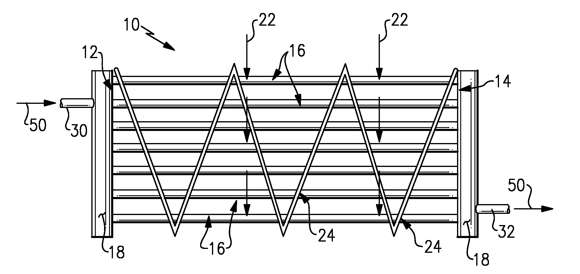
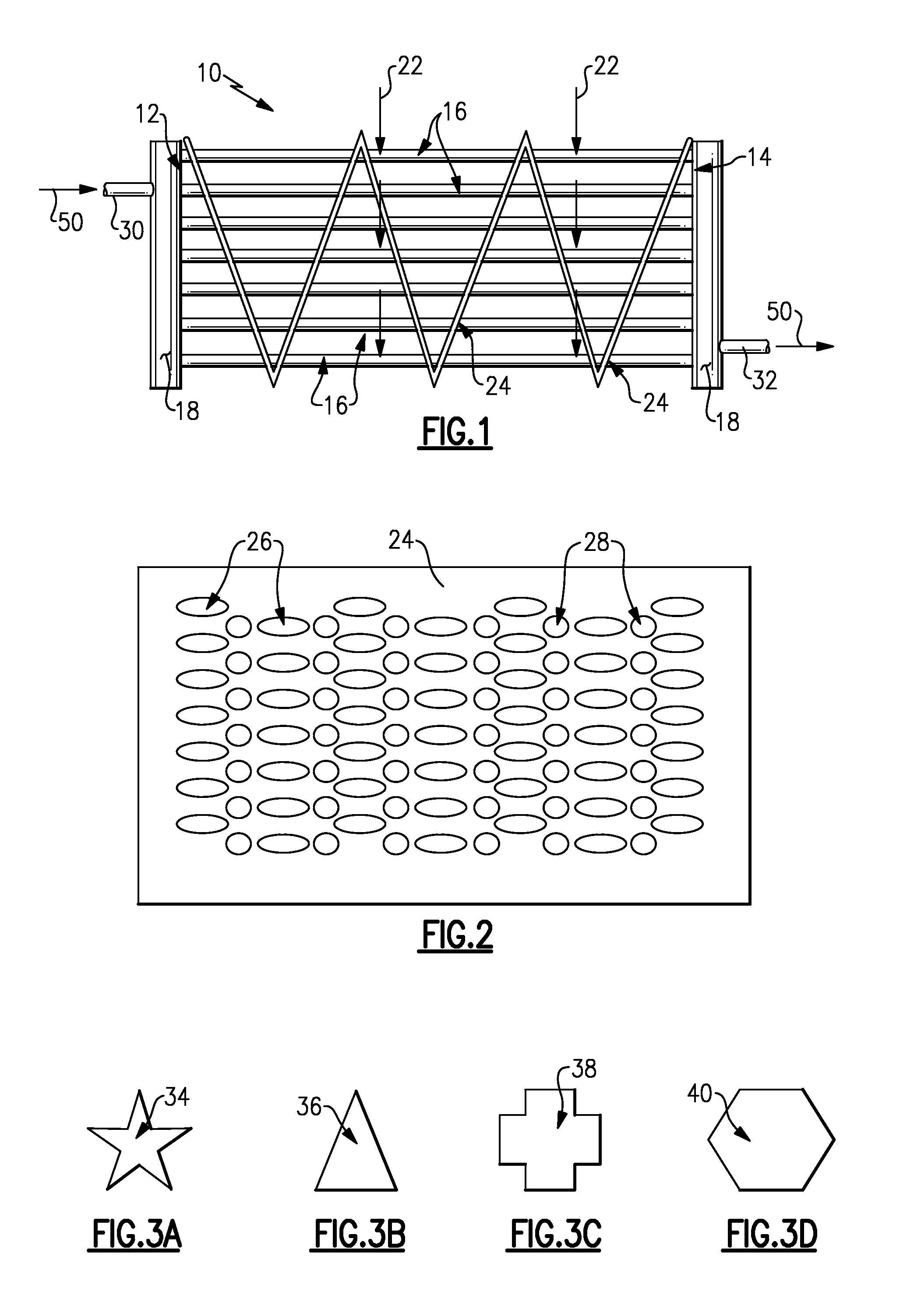
[0015]Referring to FIG. 1, an intercooler assembly 10 includes a first end plate 12 and a second end plate 14. Extending between the end first end plate 12 and the second end plate 14 are a plurality of plastic tubes 16. The plastic tubes 16 are secured to the end plates 12, 14 to provide the desired seal between the end plates 12, 14 and the ends of the tubes 16. This can be achieved by laser welding or another suitable method.

[0016]A first tank 18 is attached to the first end plate 12 and a second tank 20 is attached to the second end plate 14. The first tank 18 includes an inlet opening 30 providing an inlet for a cooling fluid 50 and the second tank 20 includes an outlet opening 32 providing an outlet of the cooling fluid 50. The cooling fluid 50 follows a path through the first tank 18, the plastic tubes 16 and the second tank 20.

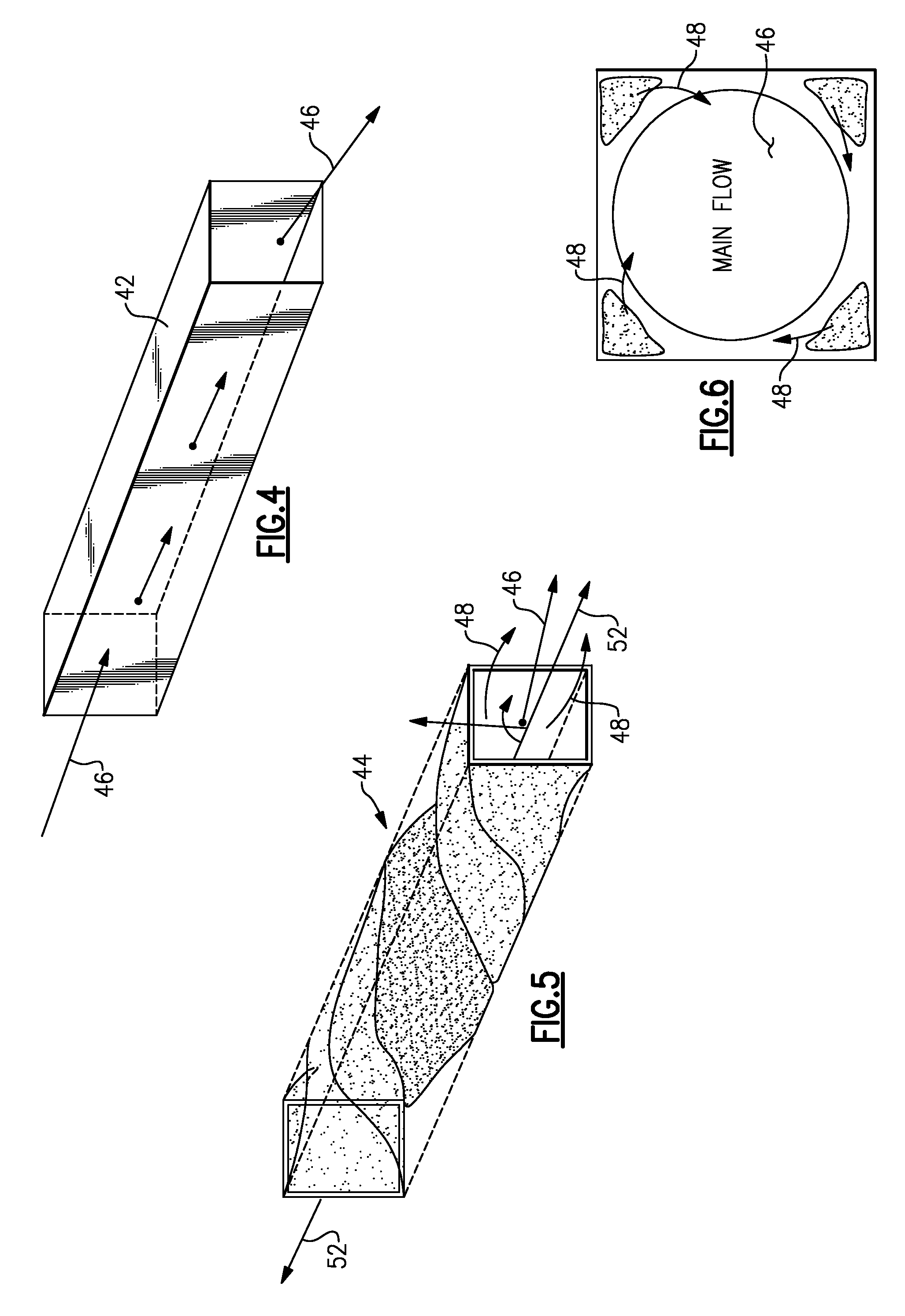
[0017]The air which is to be cooled (or charge air) flows over the plastic tubes 16 in a direction indicated with arrows 22 perpendicular to the fluid...


PUM

PropertyMeasurementUnit
Angleaaaaaaaaaa
Lengthaaaaaaaaaa
Shapeaaaaaaaaaa

Abstract

An intercooler comprises a plurality of plastic cooling tubes extending between a first end plate and a second end plate and a baffle arranged in the intercooler and extending at least partially between the first end plate and the second end plate. The baffle comprises a plurality of first openings for receiving a respective plastic cooling tube, the baffle further comprising a plurality of second openings arranged between the first openings. The second openings permit air to flow through the intercooler whilst creating turbulence in the air flow which increase the thermal transfer between the air and the tubes increasing the efficiency of the intercooler.

Description

CROSS REFERENCE TO RELATED APPLICATION[0001]The application claims priority to U.S. Provisional Application No. 60 / 886,152 filed on Jan. 23, 2007.BACKGROUND OF THE INVENTION[0002]This invention generally relates to an intercooler for use in a motor vehicle. More particularly, this invention relates to a plastic intercooler.[0003]An intercooler is a heat exchanger for transferring heat from one fluid to another fluid that is not physically in contact. One example application of an intercooler is for cooling the charge air exiting the compressor of an air charging device such as a turbocharger. An intercooler is desired to cool to and reduce the volume of the charge air so that more air can be introduced into the cylinders of an engine. The hot charge air is directed through a plurality of tubes over which cooling air flows.[0004]A conventional intercooler includes a plurality of tubes that span between manifolds or tanks on each end. The tanks typically comprise an open internal volu...

Claims


Application Information

Patent Timeline
IPC IPC(8): F28F9/02
CPCF02B29/0462F28D7/1653F28D7/1684F28D2021/0082F28F1/025F28F2009/228F28F9/0131F28F9/22F28F13/12F28F21/062Y02T10/146F28F1/04Y02T10/12
Inventor BAYLIS, BOBBYE KAYEDALY, PAUL D.MCLEAN, IAN R.HAWORTH, ROY
Owner MAHLE INT GMBH
Why Eureka
Try Eureka