Power tool

a technology of power tools and gear mechanisms, applied in the field of power tools, can solve the problems of troublesome operation, difficulty in widening the difference between the speed reduction ratio of one planetary gear mechanism and the speed reduction ratio of the other planetary gear mechanism, and achieve the effect of increasing the operability of changing

Inactive Publication Date: 2008-07-24
MAKITA CORP
View PDF17 Cites 38 Cited by
  • Summary
  • Abstract
  • Description
  • Claims
  • Application Information

AI Technical Summary

Benefits of technology

[0008]Accordingly, it is an object of the present invention to provide a technique that contributes to increased operability in changing the rotational speed of a spindle in a power tool in which the rotational speed of the spindle can be changed in three levels by utilizing a planetary gear mechanism.
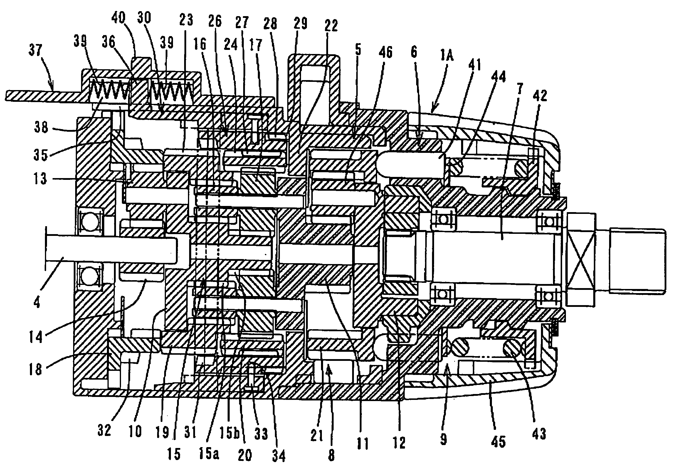
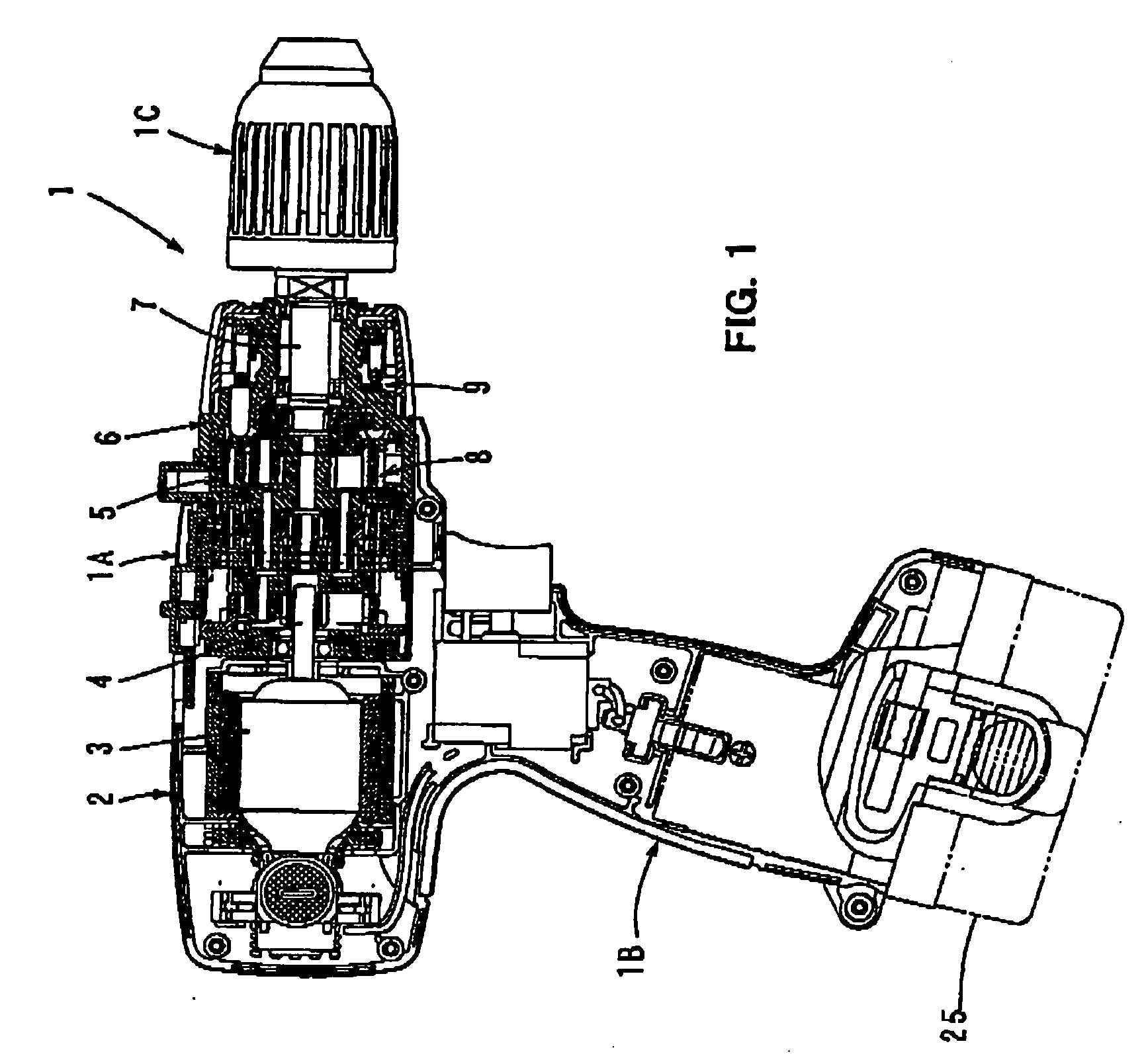
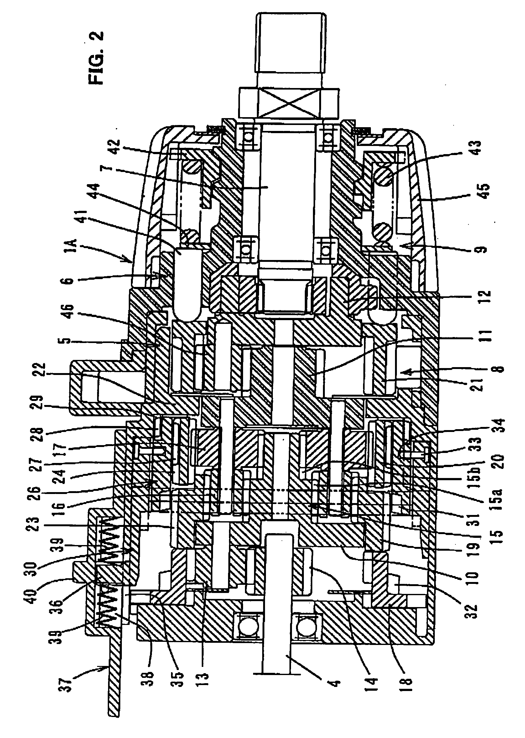
[0011]The speed changing part can move among first to third speed change positions. In the first speed change position, the speed changing part locks the first internal gear of the first gear train to the tool body and thus prevents the first internal gear from rotating, while allowing the second internal gear of the second gear train to rotate without tacking the second internal gear to the tool body. In the second speed change position, the speed changing part locks the second internal gear to the tool body and thus prevents the second internal gear from rotating, white allowing the first internal gear to rotate without locking the first internal gear to the tool body. In the third speed change position, the speed changing part connects the first and second internal gears together and allows the first and second internal gears to rotate together without locking the first and second internal gears to the tool body. When the speed changing part is placed in the first speed change position, the carrier is rotated at a predetermined first speed which is defined by a speed reduction ratio of the first gear train. When the speed changing part is placed in the second speed change position, the carrier is rotated at a predetermined second speed which is defined by a speed reduction ratio of the second gear train and is faster than the first speed. When the speed changing part is placed in the third speed change position, the carrier is rotated together with the first and second sun gears at a predetermined third speed faster than the second speed. Further, the first speed change position is located on one end side in the sliding direction of the speed changing part, the second speed change position is located on the other end side, and the third speed change position is located in an intermediate position between the first and second speed change positions.
[0012]According to the invention, the rotational speed of the carrier or the rotational speed of the spindle can be changed in three levels, or the first speed, the second speed faster than the first speed and the third speed faster than the second speed, by sliding the speed changing part among the first, second and third speed change positions. In a construction in which the rotational speed of the spindle is changed in three levels by using a plurality of planetary gear mechanisms, it is desired to minimize the outside diameter of the internal gear in order to realize reduction in size of the power tool. In order to meet such a demand, it is difficult to widen the difference between the speed reduction ratio of one planetary gear mechanism and the speed reduction ratio of the other planetary gear mechanism. Therefore, it is difficult to provide a large difference between the speed of rotation at the first speed and the speed of rotation at the second speed. On the other band, it is easy to provide a large difference between the speed of rotation at the second speed and the speed of rotation at the third speed. Therefore, in actual operation by using the power tool, the frequency of shifting from the first speed to the second speed or from the second speed to the first speed in which the speed difference is small is extremely lower than the frequency of shifting from the first speed to the third speed or from the second speed to the third speed in which the speed difference is large.
[0013]According to the invention, the third gear position in which the spindle is rotated at the third speed is located in an intermediate position in the sliding direction of the speed changing part The first speed change position in which the spindle is rotated at the first speed is located on one side of the third speed change position, and the second speed change position in which the spindle is rotated at the second speed is located on the other side of the third speed change position. Therefore, during processing operation by using the power tool, shifting operation between the first and third speeds which is frequently performed can be done without the need to go through the second speed area each time. Further, shifting operation between the second and third speeds which is also frequently performed can be done without the need to go through the first speed area. Therefore, shifting operation for speed change can be facilitated, so that ease of use can be unproved.
[0014]As one aspect of the invention, the rotational speed of the carrier may preferably be set such that the speed difference between the first and second speeds is smaller than the speed difference between the second and third speeds. With this construction, the difference between the speed reduction ratio of the first gear train which is used to obtain the first speed and the speed reduction ratio of the second gear train which is used to obtain the second speed can be reduced. In other words, the outside diameter of the internal gear forming the planetary gear mechanism can be reduced. As a result, the outside dimensions of the tool body that houses the planetary gear mechanism can be reduced, so that the size of the power tool can be reduced.
[0016]According to this aspect of the invention, with the construction in which the engagement portions are provided on both end portions of the switching member in the direction of travel and engage with the tool body, thereby preventing the first internal gear or the second internal gear from rotating, the switching member can be connected to the sliding member at a connecting point formed in the intermediate position of the switching member in the direction of travel With this construction, shifting operation can be smoothly performed without strongly pushing the switching member.

Problems solved by technology

Under such a constraint, it is difficult to widen the difference between the speed reduction ratio of one planetary gear mechanism and the speed reduction ratio of the other planetary gear mechanism.
As a result, it is rendered difficult to widen the difference m speed of the spindle between during rotation at low speed in which either one of the internal gears is locked to the housing and prevented from rotating, and during rotation at medium speed in which the other internal gear is locked to the housing and prevented from rotating.
Therefore, such an operation is troublesome, and further improvement is desired in this respect.

Method used


Image

  • Power tool
  • Power tool
  • Power tool

Examples


Embodiment Construction

[0022]Each of the additional features and method steps disclosed above and below may be utilized separately or in conjunction with other features and method steps to provide and manufacture improved power tools and method for using such power tools and devices utilized therein. Representative examples of the present invention, which examples utilized many of these additional features and method steps in conjunction, will now be described in detail with reference to the drawings. This detailed description is merely intended to teach a person skilled in the art further details for practicing preferred aspects of the present teachings and is not intended to limit the scope of the invention. Only the claims define the scope of the claimed invention. Therefore, combinations of features and steps disclosed within the following detailed description may not be necessary to practice the invention in the broadest sense, and are instead taught merely to particularly describe some representativ...


PUM


Abstract

It is an object of the invention to provide a technique that contributes to increased operability in changing the rotational speed of a spindle in a power tool b which the rotational speed of the spindle can be changed in three levels by utilizing a planetary gear mechanism. A representative power tool is characterized in that the third gear position in which the spindle is rotated at the third speed is located in an intermediate position in the sliding direction of the speed changing part The first speed change position in which the spindle is rotated at the first speed is located on one side of the third speed change position, and the second speed change position in which the spindle is rotated at the second speed is located on the other side of the third speed change position. Therefore, during processing operation by using the power tool, shifting operation between the first and third speeds which is frequently performed can be done without the need to go through the second speed area each time. Further, shifting operation between the second and third speeds which is also frequently performed can be done without the need to go through the first speed area. Therefore, shifting operation for speed change can be facilitated, so that ease of use can be improved.

Description

BACKGROUND OF THE INVENTION[0001]1. Field of the Invention[0002]The present invention relates to a power tool such as an electric driver and an electric driver drill in which a rotational speed of a spindle can be changed in three levels by utilizing a planetary gear mechanism.[0003]2. Description of the Related Art[0004]An electric driver drill is known in which the rotational speed of a spindle can be changed in three levels, or a predetermined first speed (hereinafter refers to as “low speed”), a second speed fester than the first speed (hereinafter refers to as “medium speed”) and a third speed faster than the second speed (hereinafter refers to as “high speed”). In this electric driver drill, a plurality of planetary gear mechanisms are disposed in series in the axial direction between an output shaft of a motor that is housed within a housing and a spindle that is disposed in a tip end region (front end region) of the housing. Further, die planetary gear mechanisms are constru...

Claims


Application Information

Patent Timeline
Patent Type & Authority Applications(United States)
IPC IPC(8): B23Q5/02
CPCB25F5/001F16H2200/201F16H2200/0039F16H3/66
Inventor KUROYANAGI, TAKAOABE, HIDEKI
Owner MAKITA CORP
Why Eureka
Try Eureka