Method of using infrared thermal imager to diagnose eye diseases and the device thereof

a thermal imager and infrared technology, applied in the field of infrared thermal imager to diagnose eye diseases and the device thereof, can solve the problems of long testing time, low repeatability, patient fear and discomfort, etc., and achieve the effect of accurately taking the thermal image of the cornea

Inactive Publication Date: 2008-07-24
UNITED INTEGRATED SERVICES
View PDF6 Cites 20 Cited by
  • Summary
  • Abstract
  • Description
  • Claims
  • Application Information

AI Technical Summary

Benefits of technology

[0030]The above-mentioned device further includes: a visible-light camera for simultaneously taking the image of the surface of the patient's cornea; a display connected to the visible-light camera for playing the captured cornea image; and a reflector disposed between the eye s

Problems solved by technology

The invasiveness in the traditional tests for diagnosing the dry eye syndrome is likely to cause fear and disco

Method used


Image

  • Method of using infrared thermal imager to diagnose eye diseases and the device thereof
  • Method of using infrared thermal imager to diagnose eye diseases and the device thereof
  • Method of using infrared thermal imager to diagnose eye diseases and the device thereof

Examples


Embodiment Construction

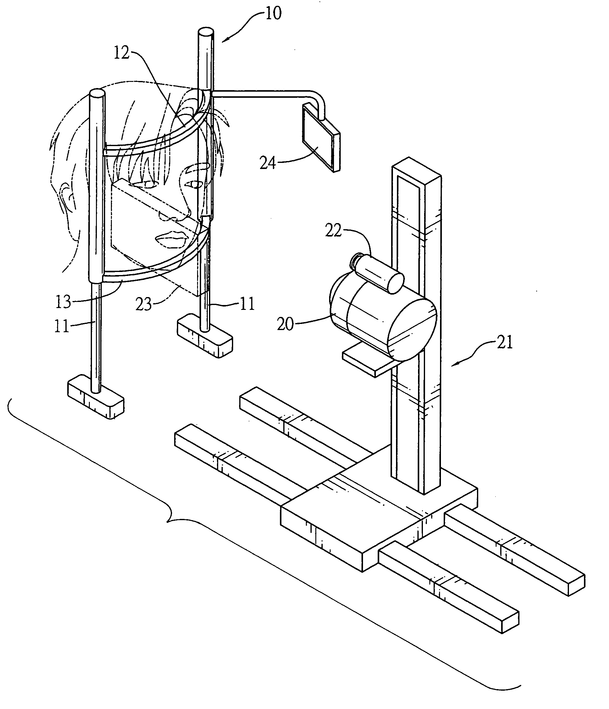
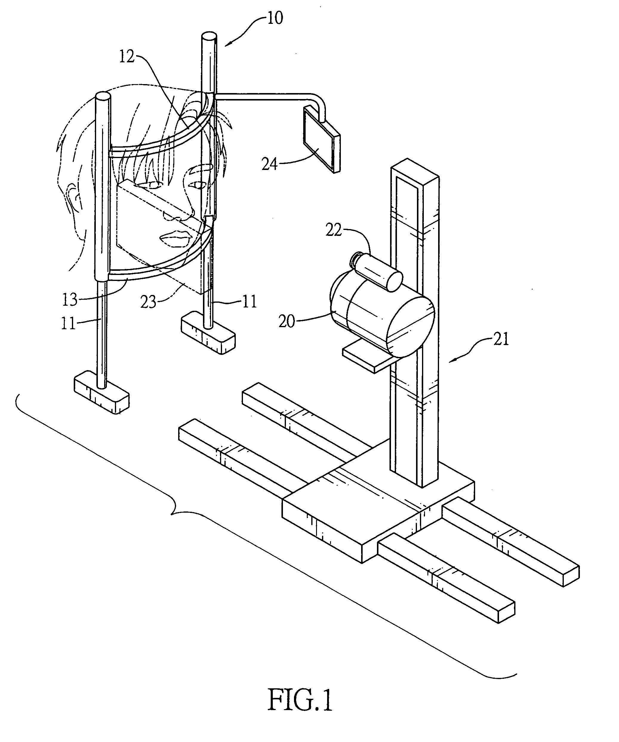
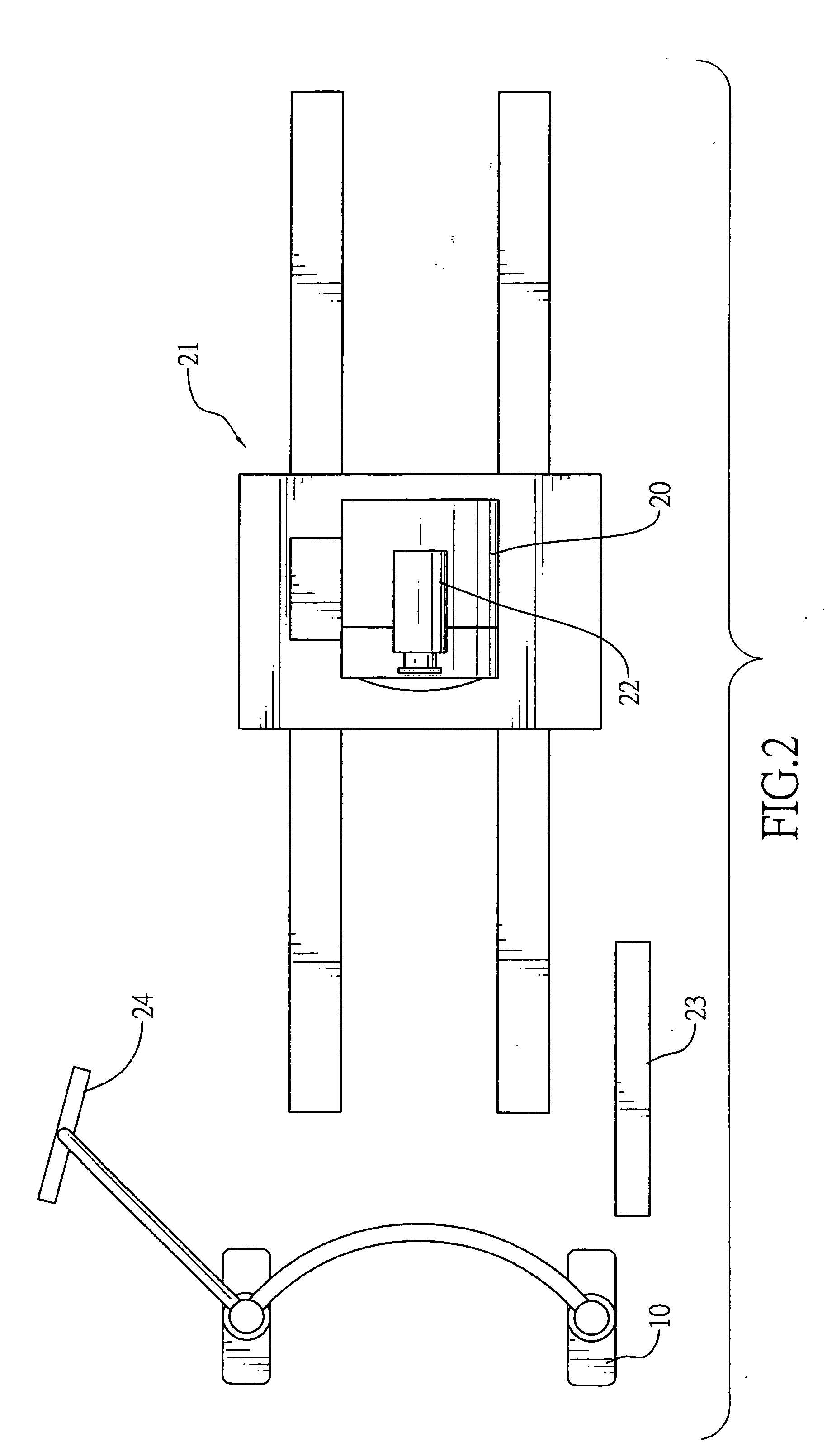
[0036]A system according to an embodiment of the invention is shown in FIG. The system includes a fixture 10 for a patient to rest his / her head, an infrared thermal imager 20, and a converting unit (not shown in the drawing). The infrared thermal imager 20 is connected to a computer system 40 (not shown in the drawing) via the converting unit.

[0037]The fixture 10 is provided with a forehead rest 12 and a lower jaw support 13 on the upper and lower ends of two parallel bars 11, respectively, for the patient to rest his / her head during the test. The patient puts his / her lower jaw on the lower jaw support 13 and his / her head against the forehead rest 12. In addition to fixing the head, the fixture also fixes the eyesight to a specific direction.

[0038]The infrared thermal imager 20 can be a focal plane array (FPA). It is installed opposite to the fixture 10 for taking the thermal images of the surface of the patient's cornea. In this embodiment, the infrared thermal imager 20 is mounted...


PUM


Abstract

A method of using infrared thermal imager to diagnose eye diseases including the dry eye syndromeuses an infrared thermal imager to take the surface image of the eyeball of the patient. Temperature variation at a specific position of the cornea of the eyeball is precisely measured in a unit time. An attenuation coefficient K of a temperature dropping curve and a temperature difference ΔT are obtained from the temperature variation. Optimized curves of K and ΔT are provided for the doctor to diagnose the patient's eye disease.

Description

BACKGROUND OF THE INVENTION[0001]1. Field of the Invention[0002]The invention relates to a method of using an infrared thermal imager to diagnose eye diseases and the device thereof. In particular, the invention relates to the technique of using an infrared thermal imager to take the image of the patient's eye and obtain the surface temperature variation of the eye to diagnose the eye diseases (including the dry eye syndrome).[0003]2. Description of Related Art[0004]The human eye has a tear layer protecting the surface of the cornea. The tear layer includes from inside out a mucus layer, an aqueous layer, and a lipid layer. The lipid layer on the outer surface of the eye is formed by the tarsal gland. The aqueous layer in the middle is produced by the lachrymal and accessory lachrymal glands. The inner mucus layer is produced by the conjunctival goblet cells. The functions of the three layers are complementary to one another. The lipid layer prevents the evaporation of water. The mu...

Claims


Application Information

Patent Timeline
IPC IPC(8): A61B3/10
CPCA61B3/101A61B5/01A61B3/14
Inventor CHANG, DAVID O.CHIANG, KENNY HUI-HUACHEN, KO-HUA
Owner UNITED INTEGRATED SERVICES
Why Eureka
Try Eureka