Heat spreader with vapor chamber defined therein

a heat spreader and vapor chamber technology, which is applied in lighting and heating apparatus, cooling/ventilation/heating modification, semiconductor devices, etc., can solve the problem of not meeting the increased heat dissipation requirement of the cpu

Inactive Publication Date: 2008-07-24
HON HAI PRECISION IND CO LTD
View PDF13 Cites 70 Cited by
  • Summary
  • Abstract
  • Description
  • Claims
  • Application Information

AI Technical Summary

Problems solved by technology

However, as the CPU operates faster and faster, and, therefore generates larger and larger amount of heat, the conventional...

Method used


Image

  • Heat spreader with vapor chamber defined therein
  • Heat spreader with vapor chamber defined therein
  • Heat spreader with vapor chamber defined therein

Examples


Embodiment Construction

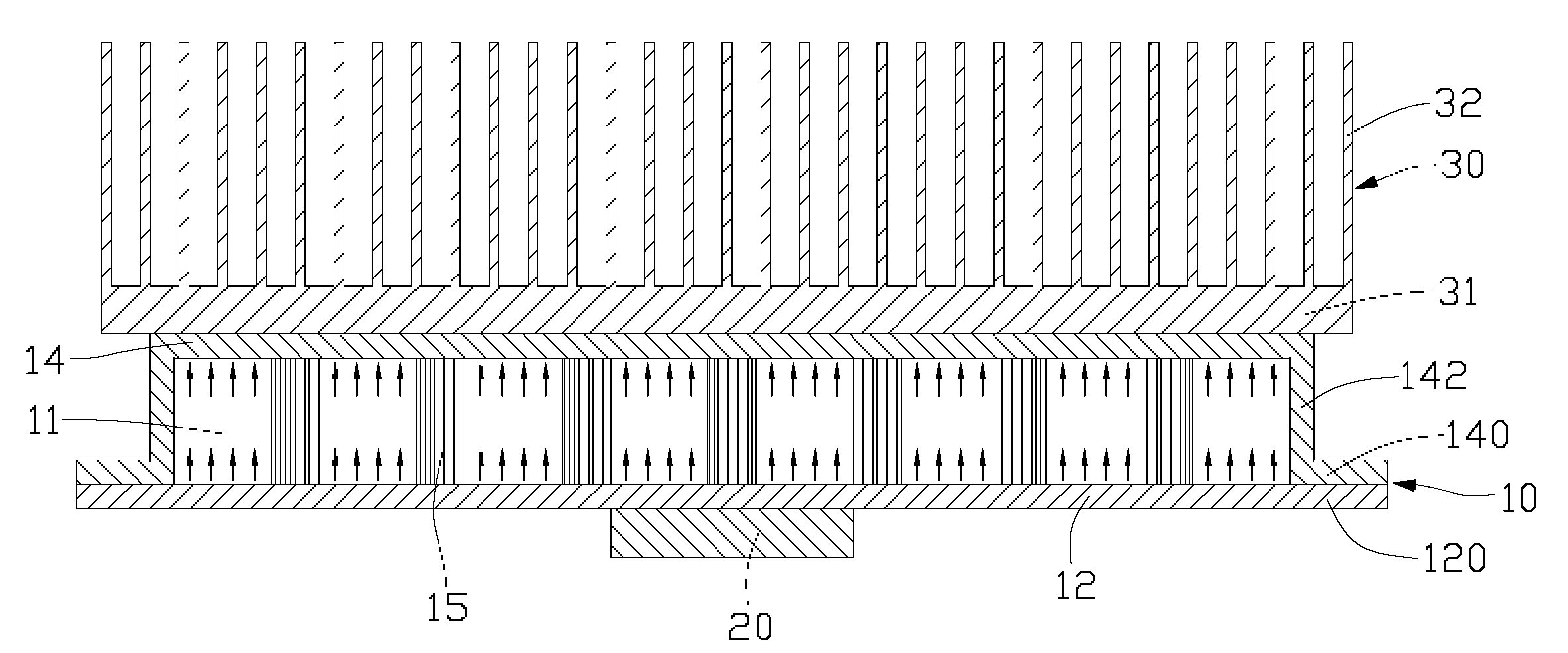
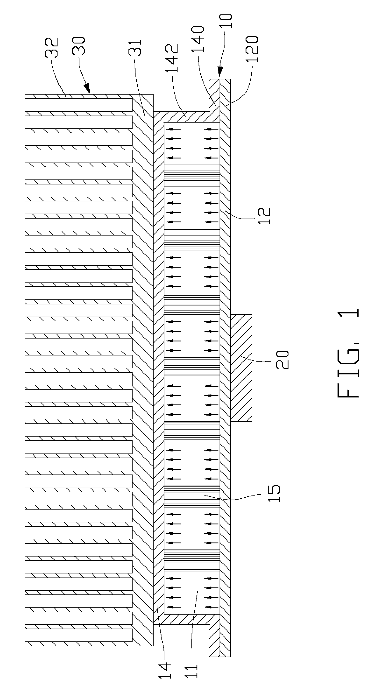
[0015]FIG. 1 is a cross-sectional view of a cooling device incorporating a heat spreader 10 in accordance with a first embodiment of the present invention. The cooling device is arranged on a heat-generating component 20, such as CPU (central process unit), VGA (Video Graphics Array), LED (light-emitting diode), NB (north bridge), and so on.

[0016]In this embodiment, the cooling device includes a heat spreader 10 and a fin-type heat sink 30 arranged on the heat spreader 10. The heat sink 30 is made of material with highly thermal conductivity, such as copper, aluminum, or their alloys. The heat sink 30 as shown in this embodiment is an extruded aluminum heat sink, including a chassis 31 and a plurality of pin fins 32 extending upwardly from the chassis 31. Apparently, the fins 32 are used for increasing the heat dissipation area of the heat sink 30. Alternatively, the fins 32 can be plate-like shaped. The fins 32 and the chassis 31 can be formed separately, and then connected togethe...


PUM


Abstract

A heat spreader includes a bottom wall (12) and a cover (14) hermetically connected to the bottom wall. Cooperatively the bottom wall and the cover define a space (11) therebetween for receiving a working fluid therein. A wick structure (15) is received in the space and thermally interconnects the bottom wall and the cover. The wick structure includes at least a carbon nanotube array, which can conduct heat from the bottom wall to the cover and draw condensed liquid of the working fluid from the cover toward the bottom wall.

Description

BACKGROUND OF THE INVENTION [0001]1. Field of the Invention[0002]The present invention relates to an apparatus for transfer or dissipation of heat from heat-generating components, and more particularly to a heat spreader having a vapor chamber defined therein.[0003]2. Description of Related Art[0004]As electronic industry continues to advance, electronic components such as central processing units (CPUs), are made to provide faster operational speeds and greater functional capabilities. When a CPU operates at a high speed, its temperature frequently increases greatly. It is desirable to dissipate the heat generated by the CPU quickly.[0005]To solve this problem of heat generated by the CPU, a heat sink is often used to be mounted on the top of the CPU to dissipate heat generated thereby. For enhancing the heat dissipation capability of the heat sink, a heat spreader is arranged between the heat sink and the CPU, which is made of a material having a heat conductivity higher than that...

Claims


Application Information

Patent Timeline
IPC IPC(8): H05K7/20
CPCF28D15/0233F28D15/046H01L23/427H01L2924/0002H01L2924/00H01L23/373
Inventor CHANG, CHANG-SHENLIU, JUEI-KHAIWANG, CHAO-HAOPEI, HSIEN-SHENG
Owner HON HAI PRECISION IND CO LTD
Why Eureka
Try Eureka