Thermocouple Assembly And Method Of Use

a technology of thermocouples and components, applied in the field of thermocouple assemblies, can solve the problems of unwanted electromotive forces and other problems, and achieve the effect of preventing excessive rod movemen

Inactive Publication Date: 2008-07-24
VESUVIUS CRUCIBLE CO
View PDF12 Cites 8 Cited by
  • Summary
  • Abstract
  • Description
  • Claims
  • Application Information

AI Technical Summary

Benefits of technology

[0015]According to a preferred embodiment of the present invention, the first ceramic element forms an inner leg and the second ceramic element forms an outer sheath. Thereby, the second ceramic element protects the first ceramic element from attacks by the molten phase. In this case, the second ceramic element is generally selected to be suitable to resist the molten phase attacks for a certain time, very suitable materials in this case are the alumina-graphite based compositions.
[0016]In the case of this embodiment, the assembly preferably further comprises an electrically insulating sleeve (preferably constituted of alumina) around the inner leg. This provides electrical insulation and helps to provide rod retention and cushioning from vibration.
[0017]In certain cases, it can also be advantageous to have a further sleeve located around the sleeve insulating the inner leg to prevent excessive rod movement (in certain applications only).

Problems solved by technology

Obviously, at the junctions between the two legs of the second and third thermocouples with the connectors of their respective measuring device, unwanted electromotive forces are also generated.

Method used


Image

  • Thermocouple Assembly And Method Of Use
  • Thermocouple Assembly And Method Of Use
  • Thermocouple Assembly And Method Of Use

Examples


Embodiment Construction

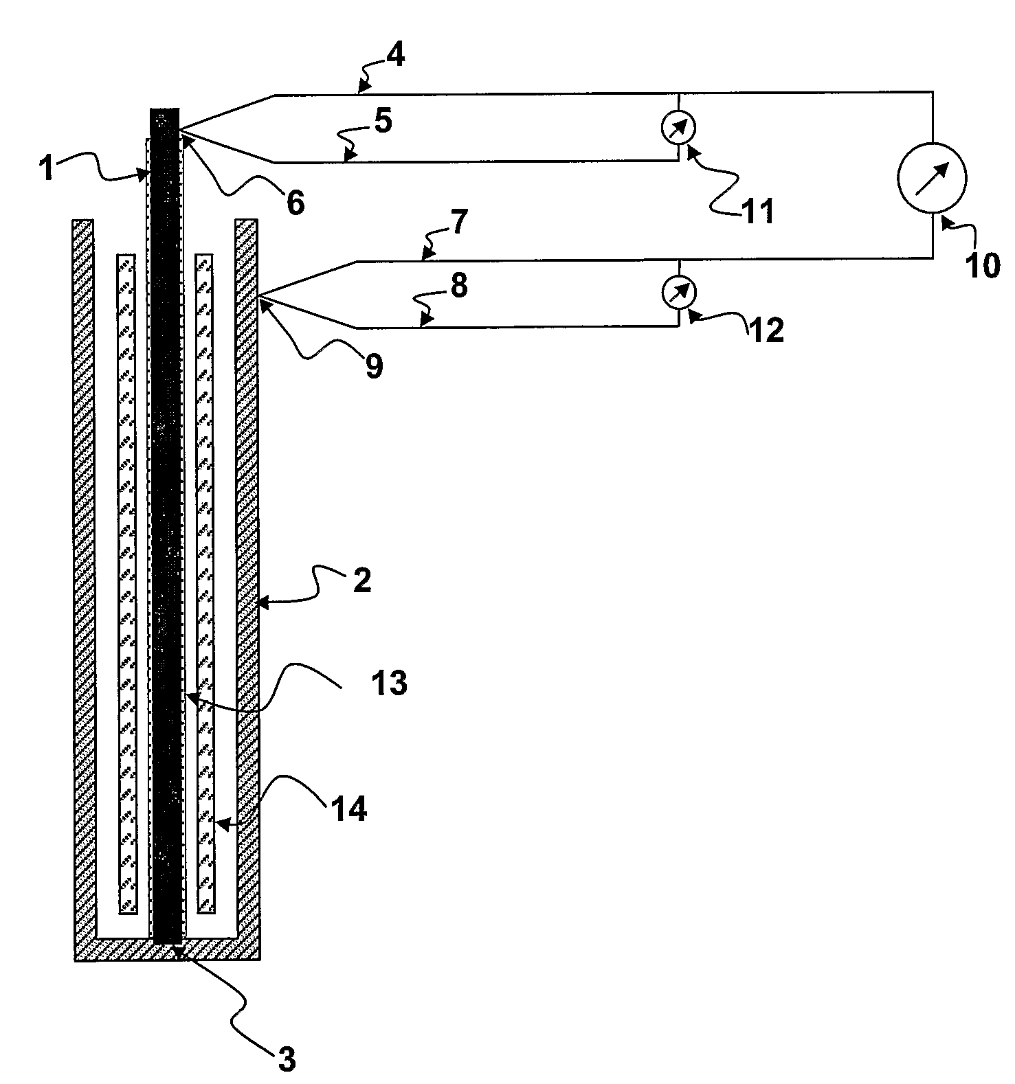
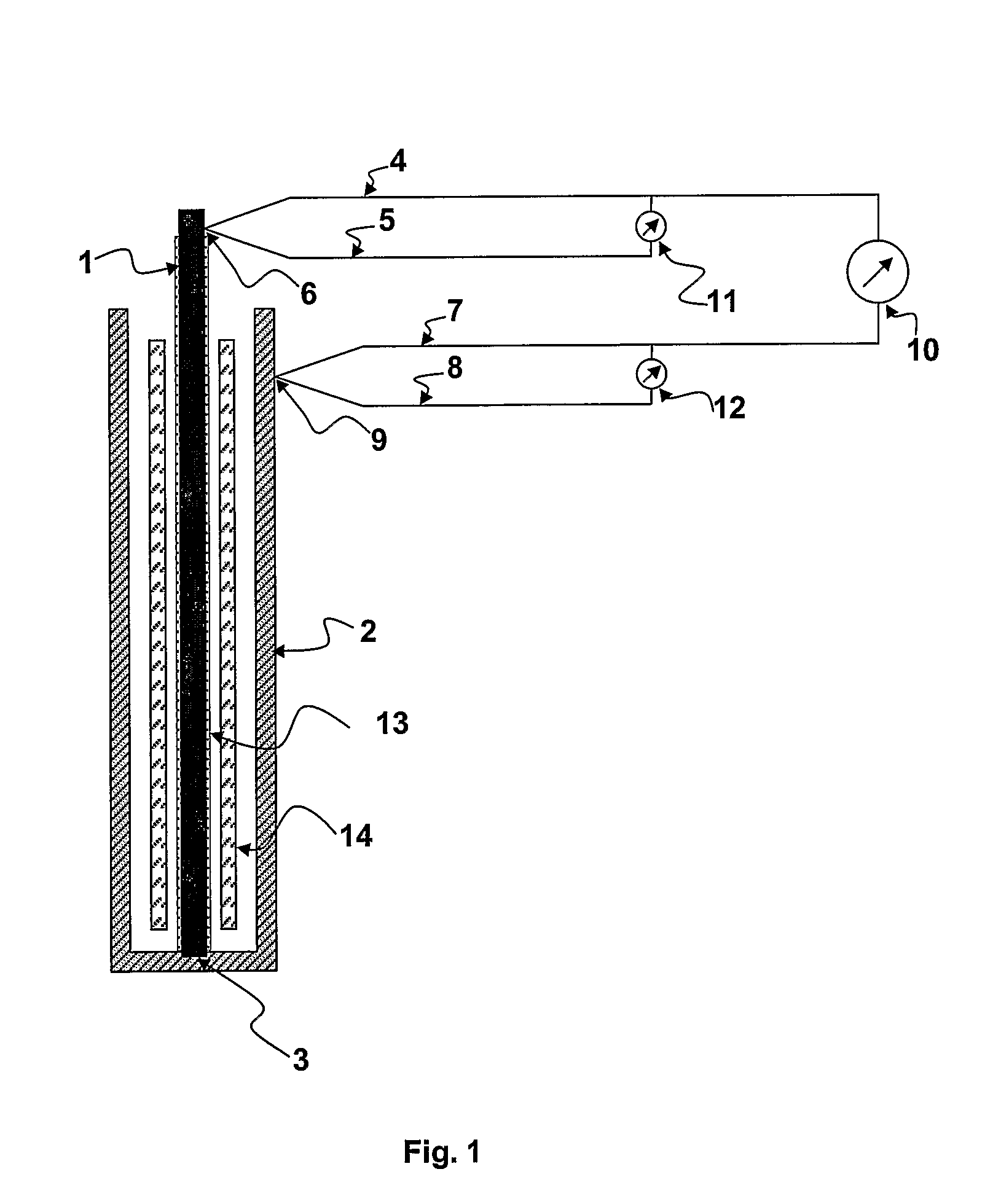
[0026]FIG. 1 schematically shows thus a thermocouple assembly for the measurement of the temperature of a molten phase according to the invention. It is constituted of first and second ceramic elements (1,2) contacting each other at a first junction (3) and forming thereby a first thermocouple. In use, the junction (3) is positioned at or under the level of the molten phase. A second thermocouple formed of two different conducting elements (4,5), preferably metallic conductors, contacting each other at a second junction (6) is located on the first ceramic element (1) (preferably around the cold end of the first ceramic element (1)). A third thermocouple formed of two differing conducting elements (7,8), preferably metallic conductors, contacting each other at a third junction (9) is located on the second ceramic element (2), (preferably around the cold end of the second ceramic element (2)). Both positive legs (4,7) or both negative legs (5,8) of the second and third thermocouples a...


PUM

PropertyMeasurementUnit
temperaturesaaaaaaaaaa
temperatureaaaaaaaaaa

Abstract

A thermocouple assembly for the continuous measurement of the temperature of a molten phase contains first and second ceramic elements contacting each other at a first junction and forming thereby a first thermocouple, a second thermocouple formed of two different conducting elements contacting each other at a second junction located on the first ceramic element and a third thermocouple formed of two different contacting elements contacting each other at a third junction located on the second ceramic element. Both positive legs or both negative legs of the second and third thermocouples are connected to a first measuring device. Both legs of the second and third thermocouple are connected respectively to a second and third measuring device as well as to a process for the measurement of the temperature of a molten phase.

Description

FIELD OF THE INVENTION[0001]The present invention concerns a thermocouple assembly for the measurement of the temperature of a molten phase (or other high temperature applications) and to a method for the measurement of the temperature of a molten phase (or other high temperature applications) using the said thermocouple assembly.BACKGROUND OF THE INVENTION[0002]It is known that dissimilar materials, when joined produce an electromotive force by the Seebeck effect in relation to the temperature of the junction between the materials. Thermocouples constituted of metals are known and have been widely used for decades. Unfortunately, the metals used for these thermocouples have a tendency to oxidize or to be chemically attacked during use so that their accuracy is not guaranteed over extended periods. It has already been described that certain non-metallic materials, for example ceramics, may also produce an electromotive force in relation to their temperature. Ceramics do not suffer t...

Claims


Application Information

Patent Timeline
Patent Type & Authority Applications(United States)
IPC IPC(8): G01K7/00
CPCG01K7/04G01K7/02H10N10/85
Inventor ROBBINS, BERNARD
Owner VESUVIUS CRUCIBLE CO
Why Eureka
Try Eureka