Low-frequency range extension and protection system for loudspeakers

a protection system and low frequency technology, applied in the direction of transducer protection circuits, limiting amplitudes, electrical devices, etc., can solve the problems of limiting the maximum acoustic output capability of the acoustic output, heat buildup, signal distortion, etc., to extend the low frequency bandwidth of the audio system

Active Publication Date: 2008-07-24
AUDYSSEY LABORATORIES
View PDF13 Cites 76 Cited by
  • Summary
  • Abstract
  • Description
  • Claims
  • Application Information

AI Technical Summary

Benefits of technology

[0033]FIG. 5 is a first method according to the present invention for extending the low frequency bandwidth of an audio system.
[0034]FIG. 6 is a second method according to the present invention for extending the low frequency bandwidth of an audio system.

Problems solved by technology

Conventional electromagnetic loudspeaker drive units have two principal limits on their maximum acoustic output capability: excursion of the cone, and heat buildup.
Excessive cone excursion adds distortion to the signal creating a desire to limit the cone excursion.
Further, the drive unit temperature rises above tolerable limits if the electrical power-handling ability of the voice coil is exceeded and there is insufficient capacity for removing the resulting heat from the coil.
Overly high temperatures ultimately result in a failure of the voice coil insulation, wire, and / or bonding of the voice coil to its former as the temperature of the internal parts becomes so great that electrical insulation and glue systems fail.
Additionally, complete loudspeaker systems, as opposed to conventional drive units alone, have additional limits imposed on them due to upper limits on velocity of air in ports, or passive radiators undergoing excessive excursion.
High velocity of air in the ports may cause extraneous noise, and passive radiator low frequency maximum excursion may be different from the maximum low frequency excursion of the principal drive units.
These increases in heat and excursion may exceed a speaker's limits.
Unfortunately, such attempts have failed to achieve the best possible fit of bandwidth extension while staying within the excursion and thermal limits of drivers.

Method used


Image

  • Low-frequency range extension and protection system for loudspeakers
  • Low-frequency range extension and protection system for loudspeakers
  • Low-frequency range extension and protection system for loudspeakers

Examples


Embodiment Construction

[0036]The following description is of the best mode presently contemplated for carrying out the invention. This description is not to be taken in a limiting sense, but is made merely for the purpose of describing one or more preferred embodiments of the invention. The scope of the invention should be determined with reference to the claims.

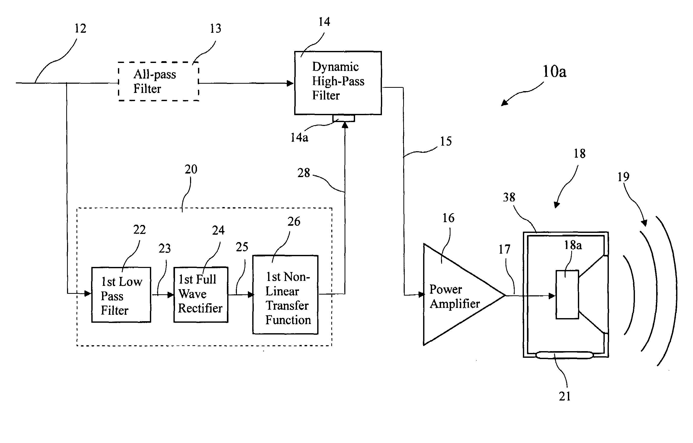
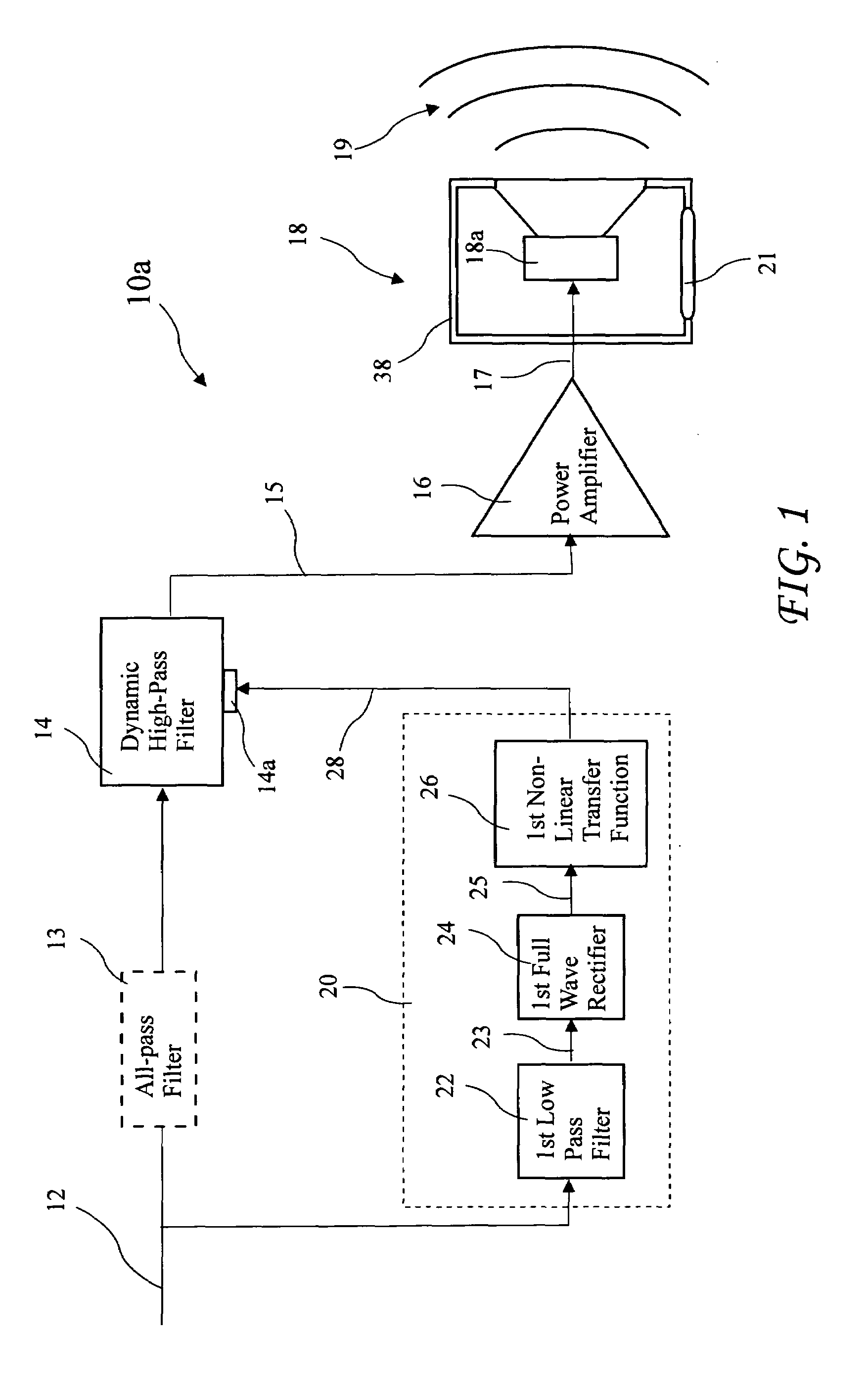
[0037]A first system 10a according to the present invention for extending low frequency performance of a loudspeaker is shown in FIG. 1. The system 10a includes a dynamic high-pass filter 14 having at least two poles and at least two zeros at the origin (which make it a high-pass filter). The dynamic high-pass filter 14 processes an unfiltered input signal 12 to generate a filtered signal 15 provided as an amplifier input signal to a power amplifier 16, and power amplifier 16 amplifies the filtered signal 15 to provide a speaker signal 17 to a loudspeaker 18. The loudspeaker 18 includes a speaker driver 18a residing in a speaker enclosure 38 and r...


PUM


Abstract

Low-frequency bandwidth extension in the form of dynamic electrical equalization may be applied to loudspeakers so long as the excursion capability of their drive units as well as velocity limits of any port(s) or excursion limits of any associated passive radiator(s), and the power limits of the drive units are not exceeded. The bandwidth extension maximizes low-frequency bandwidth dynamically such that excursion is fully utilized over a range of drive levels, without exceeding the excursion limit. Additional limiting control is available for port air velocity or passive radiator excursion, and loudspeaker drive unit electrical power. The system applies to open back, closed box, vented box, and more complex box constructions consisting of combinations of these elements for loudspeaker designs using design parameters appropriate to each system.

Description

BACKGROUND OF THE INVENTION[0001]The present invention relates to electronic signal processing for loudspeakers and in particular to extending the low-frequency capability of loudspeakers.[0002]Conventional electromagnetic loudspeaker drive units have two principal limits on their maximum acoustic output capability: excursion of the cone, and heat buildup. Excessive cone excursion adds distortion to the signal creating a desire to limit the cone excursion. Further, the drive unit temperature rises above tolerable limits if the electrical power-handling ability of the voice coil is exceeded and there is insufficient capacity for removing the resulting heat from the coil. Overly high temperatures ultimately result in a failure of the voice coil insulation, wire, and / or bonding of the voice coil to its former as the temperature of the internal parts becomes so great that electrical insulation and glue systems fail.[0003]The maximum acoustic output limits may be changed if the loudspeak...

Claims


Application Information

Patent Timeline
Patent Type & Authority Applications(United States)
IPC IPC(8): H03G11/00
CPCH04R3/08H04R3/007
Inventor HOLMAN, TOMLISON
Owner AUDYSSEY LABORATORIES
Why Eureka
Try Eureka