Low-pressure, air-based, particulate materials transfer apparatus and method

a technology of particulate materials and transfer equipment, which is applied in the field of low-pressure air-based, particulate material transfer equipment and methods, can solve the problems of increasing dramatically the manufacturing, maintenance, and especially the operational energy costs, and little evidence in the literature that any major consideration has been given, and achieves the effect of reducing electrical (or mechanical) energy requirements and reducing product friction

Inactive Publication Date: 2008-07-24
ENSENTECH
View PDF22 Cites 11 Cited by
  • Summary
  • Abstract
  • Description
  • Claims
  • Application Information

AI Technical Summary

Benefits of technology

[0012]In accordance with the present invention, an apparatus and process is presented for material handing and processing which is provided wherein any and all applicable industrial materials and foodstuffs which are of a quality and consistency which are injectable by gravity, mechanical, hydraulic, or pneumatic means into a high velocity core airflow in piping, or other encl...

Problems solved by technology

In pneumatic and slurry systems, due to product density factors and viscous friction in piping, there is the need to move many times the amount of carrier material compared to the entrained product, all of which multiplies dramatically the manufacturing, maintenance, and especially the operational energy costs.
In a very large and complex mining operation with an underground crushing and classification system the waste material is presently backfilled into a mined out area.
Wide usage of the ZVVAC+ system would change some cost elements of every single product we consume in terms of equipment manufactu...

Method used


Image

  • Low-pressure, air-based, particulate materials transfer apparatus and method
  • Low-pressure, air-based, particulate materials transfer apparatus and method
  • Low-pressure, air-based, particulate materials transfer apparatus and method

Examples


Embodiment Construction

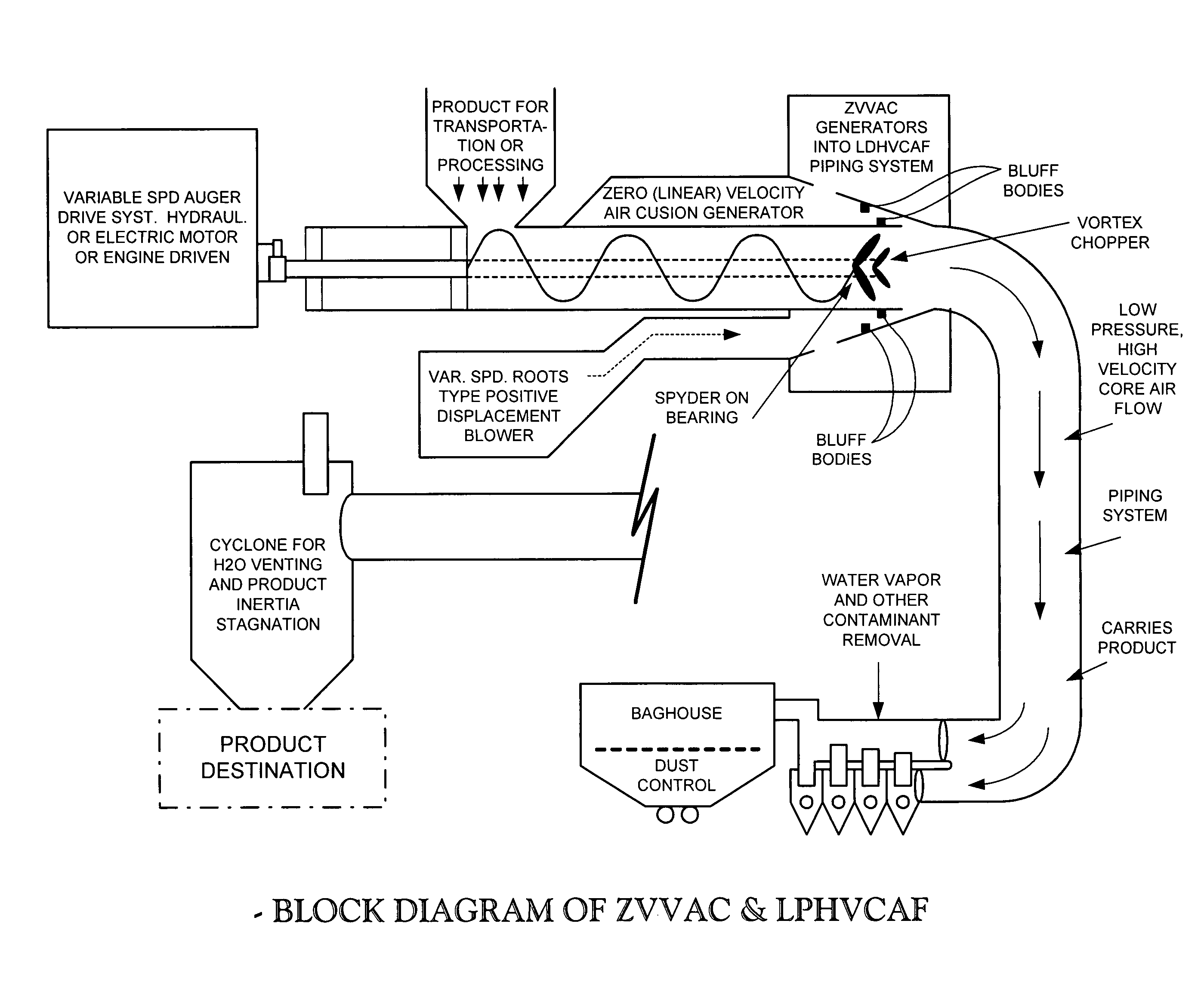
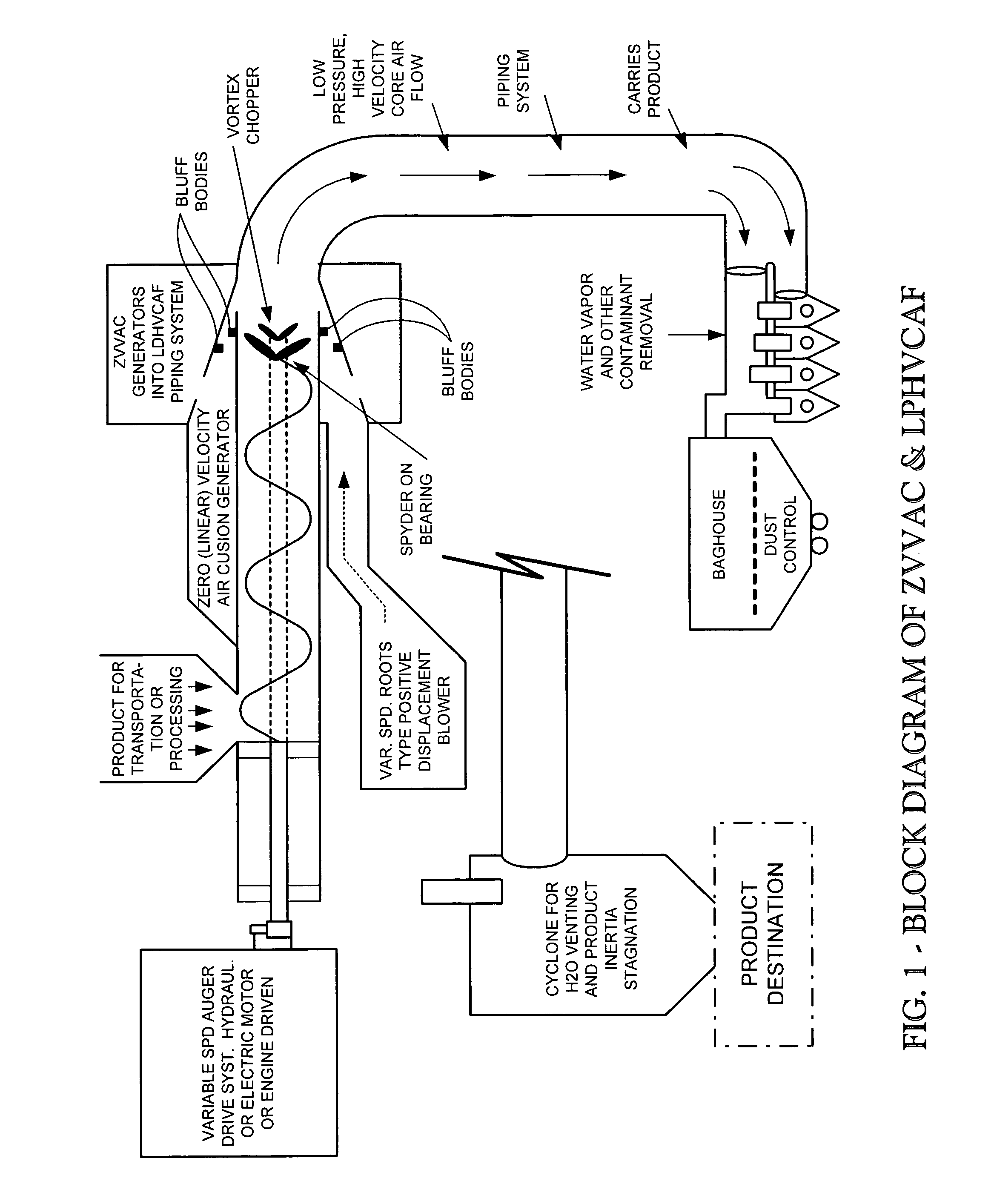
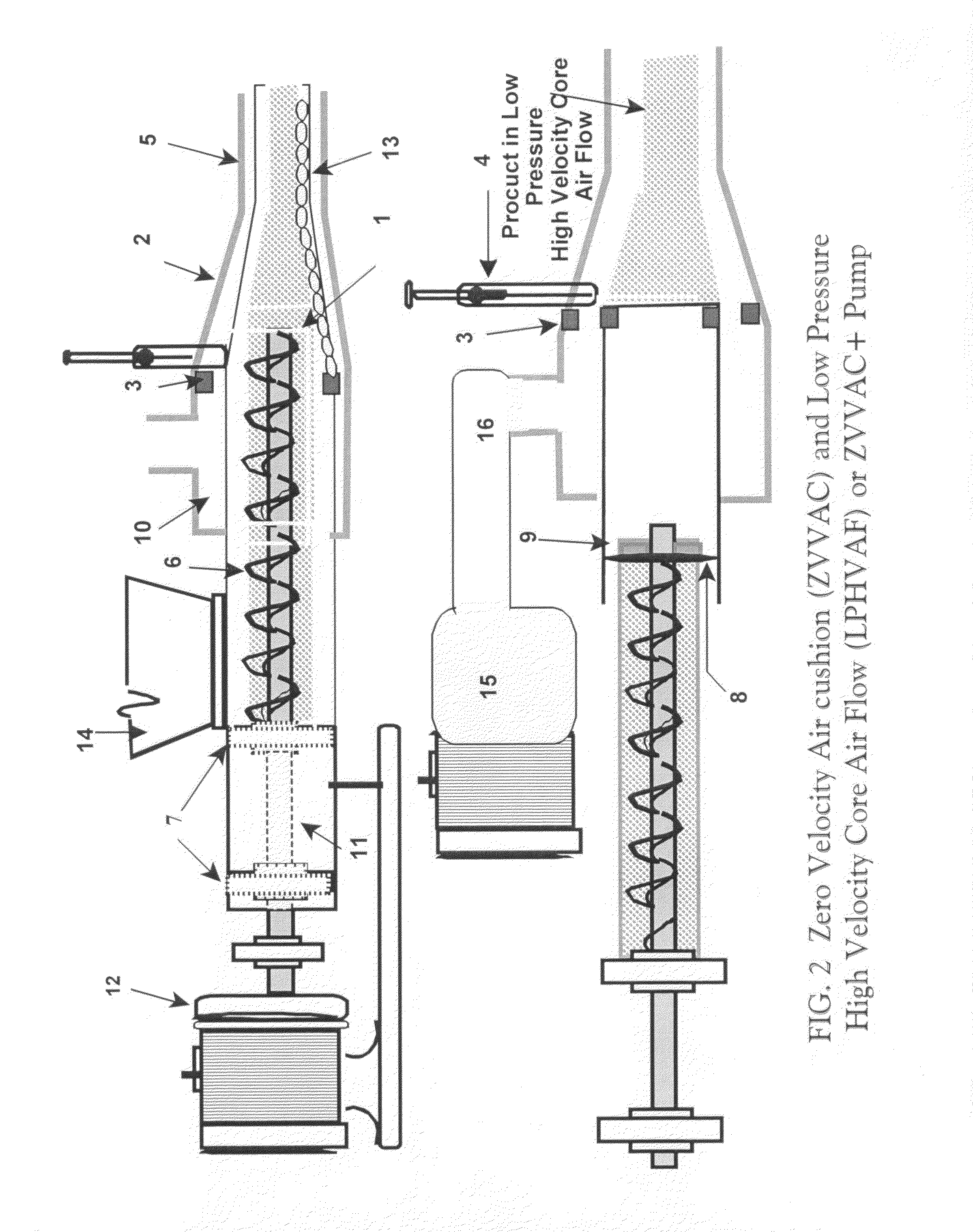
[0022]In the preferred embodiment(s) of this system, incorporation of the previously described features are utilized as they are selected from the following engineered specifications and ZVVAC+ pump features requirement list:[0023]NOTE: Since ZVVAC+ pump-systems are “product specific” the following list-items must be considered for each application, and sometimes location.[0024]1. Product line size (pipe Diameter and Pump size) as related to TPH (tons per hour) capacity and type of product being handled.[0025]2. Configuration and taper of airflow control nose cone.[0026]3. Spacing between auger barrel-vortex generator(s) and nose cone air chamber wall.[0027]4. Product velocity—air requirement-volume & velocity in the piping system.[0028]5. Product insertion velocity—determined by setting the variable speed auger RPM or product metering parameters.[0029]6. Auger pitch, vortex placement and other auger features to generate a zero linear vortex velocity air cushion on inside of product...


PUM


Abstract

This invention relates to a system, process, and the device for reducing energy usage by simplifying equipment and thus the power requirements for manufacturing, installation of the equipment required for use in the movement-transportation to/during the processing of granular particulate bulk, powder products, many liquids slurry-able materials. Many commonly identified materials will be in a granular, particulate and non agglomerative condition suitable for injection by auger or inertial gravity into an enclosed pipe or conveyance chamber. In the device, two distinct and specific air flow patterns are identified when mechanically-pneumatically established within a single, low pressure piping entity; 1. A unique self regenerating (for system length), pipe contained, Vortex air cushion, with zero linear variable velocity (ZVVAC). 2. A linear, low pressure, high velocity “core flow” of air (LPHVCF), or ZVVAC+, (the two features when combined), which carries the injected product or material thus eliminating energy consuming pipe contact within the conveying system in a frictionless, high speed environment without product degradations, where system processing-grading features are optimized specifically where system production costs, maintenance, and especially operational energy costs are reduced by 90 percent or more.

Description

PRIORITY CLAIM[0001]The present application claims priority from U.S. provisional patent application Ser. No. 60 / 860,875, filed Nov. 22, 2006, and entitled LOW-PRESSURE, AIR-BASED, PARTICULATE MATERIALS TRANSFER APPARATUS AND METHOD.BACKGROUND OF THE INVENTION[0002]The present invention is directed broadly to an improved and reduced energy requirement materials handling system for bulk engineering and foodstuffs in powder, granular, and liquid forms wherein these materials can be injected into a pneumatic air-operated device by whatever means is required. While materials are in the high air flow core, natural stratification and dehydration occur. These factors may be optimized at the cyclone or grading flow-system terminus-through the use of various classification, separation devices or features.[0003]The present invention is directed more specifically to; 1. Reducing system manufacturing costs through simplification, 2. the reduction on operational energy costs, 3. the maintenance ...

Claims


Application Information

Patent Timeline
IPC IPC(8): B65G53/08B65G53/34B65G53/48
CPCB65G53/08B65G53/58B65G53/48Y10T137/85978
Inventor WOOD, GRANT R.
Owner ENSENTECH
Why Eureka
Try Eureka