Connector for use in substrate

a technology for connecting components and substrates, applied in the direction of connection contact material, connection device connection, printed circuit aspects, etc., can solve the problem of air trapped in the bag-shaped space, and achieve the effect of facilitating air venting and simplifying molding materials

Inactive Publication Date: 2008-07-24
SUMITOMO WIRING SYST LTD
View PDF5 Cites 8 Cited by
  • Summary
  • Abstract
  • Description
  • Claims
  • Application Information

AI Technical Summary

Benefits of technology

[0008]There is a fear that air will be trapped in the bag-shaped space as the sealing material is introduced. However, air in the bag-shaped space of the blind alley will be discharged to the outside through the air vent in the covering wall. The absence of air in the bag-shaped space of the blind alley ensures a large contact area between the housing and the potting material. Therefore, a required adhesion is assured and the connector is waterproof.
[0009]A substrate-fixing portion preferably projects out from the side walls to be fixed to the printed-circuit board. A fixing hole is formed through the substrate-fixing portion for receiving a fixing member. The fixing member extends parallel to the air vent. The alignment of the fixing hole parallel to the air vent enables the die-cutting direction of the air vent and the fixing hole to be coincident with each other. Consequently, both holes can be molded at one time by one molding material. Thus it is possible to simplify the molding material and easily form the air vent.
[0010]The air vent preferably is a small hole disposed near a rear surface of the body of the housing. The disposition of the air vent near the rear of the body assures a secure discharge of air trapped between the body of the housing and the covering wall to the outside. Further, the small size of the air vent ensures a necessary strength for the covering wall.
[0011]The invention also relates to a method of assembling a connector for use with a substrate. The method includes placing the housing on the printed-circuit board and inside a case with the open surface of the case facing up and with a front surface of the housing facing up. The method proceeds by charging a sealing material into a bag-shaped space of the case and removing air in the bag-shaped space through an air vent by drawing a vacuum on the case. The vacuum drawing ensures a secure discharge of the air trapped inside the bag-shaped space to the outside.

Problems solved by technology

There is a fear that air will be trapped in the bag-shaped space as the sealing material is introduced.

Method used


Image

  • Connector for use in substrate
  • Connector for use in substrate
  • Connector for use in substrate

Examples


Embodiment Construction

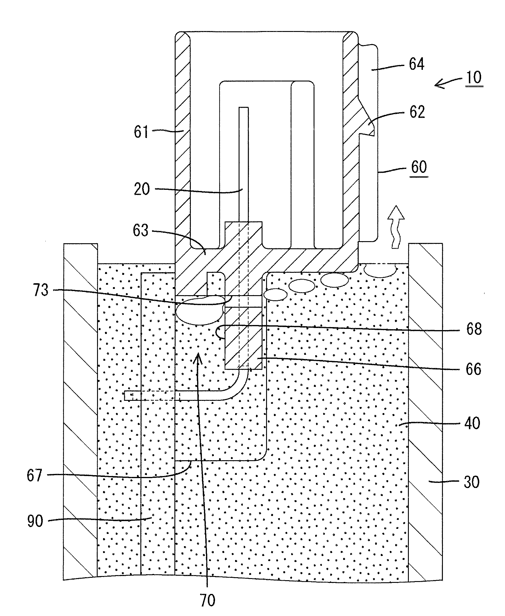
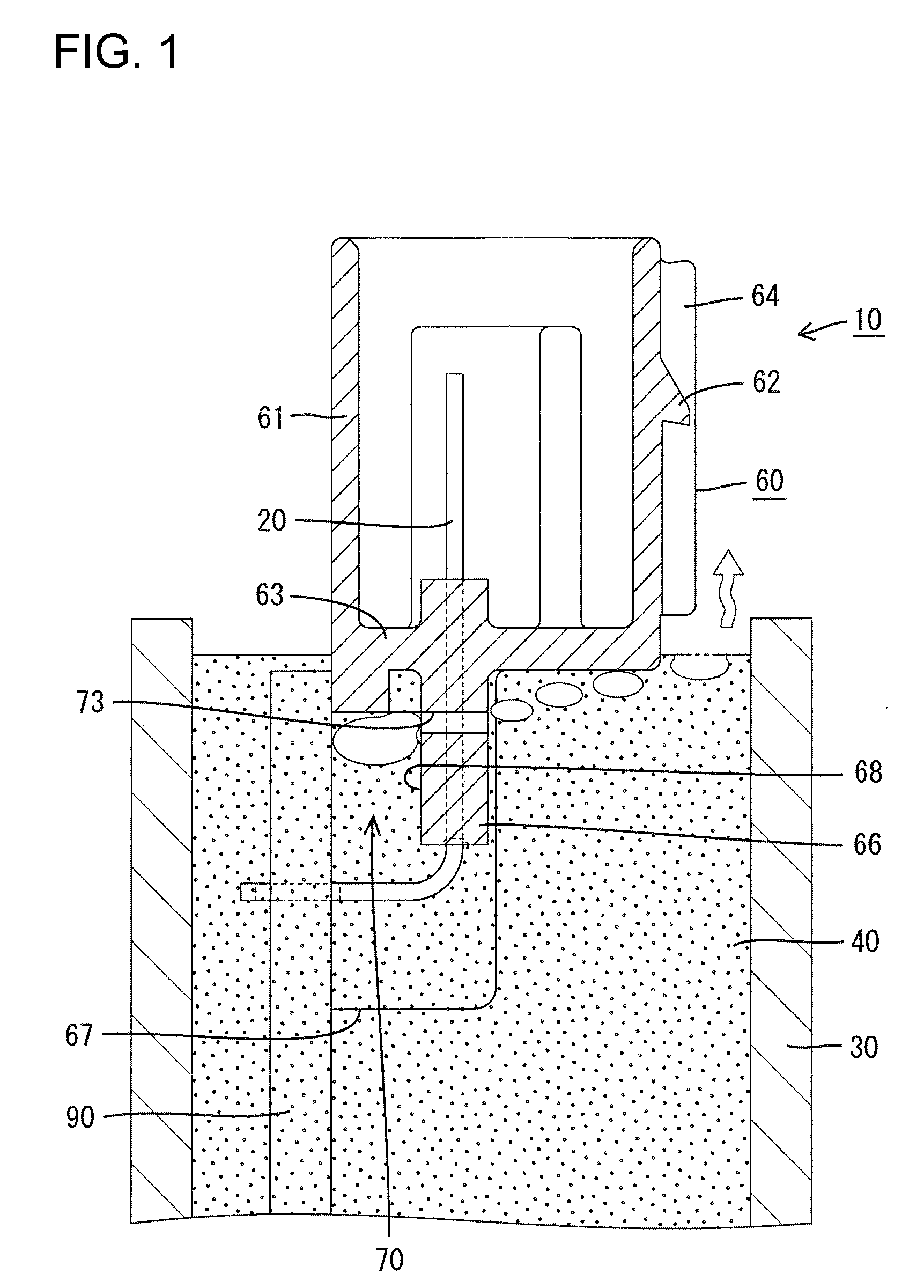
[0017]A connector in accordance with the invention is identified generally by the numeral 10 in FIGS. 1 through 5. The connector 10 is intended for use on a substrate and has a terminal fitting 20 and a housing 60 to which the terminal fitting 20 is mounted. The housing 60 can be connected to a mating housing (not shown). The housing 60 can be placed on a printed-circuit board 90 and both the housing 60 and the printed-circuit board 90 can be accommodated inside a case 30. A potting material 40 is introduced into the case 30 to provide a liquid-tight sealing in the case 30. In the description made below, the fit-on side of both housings is referred to as the front.

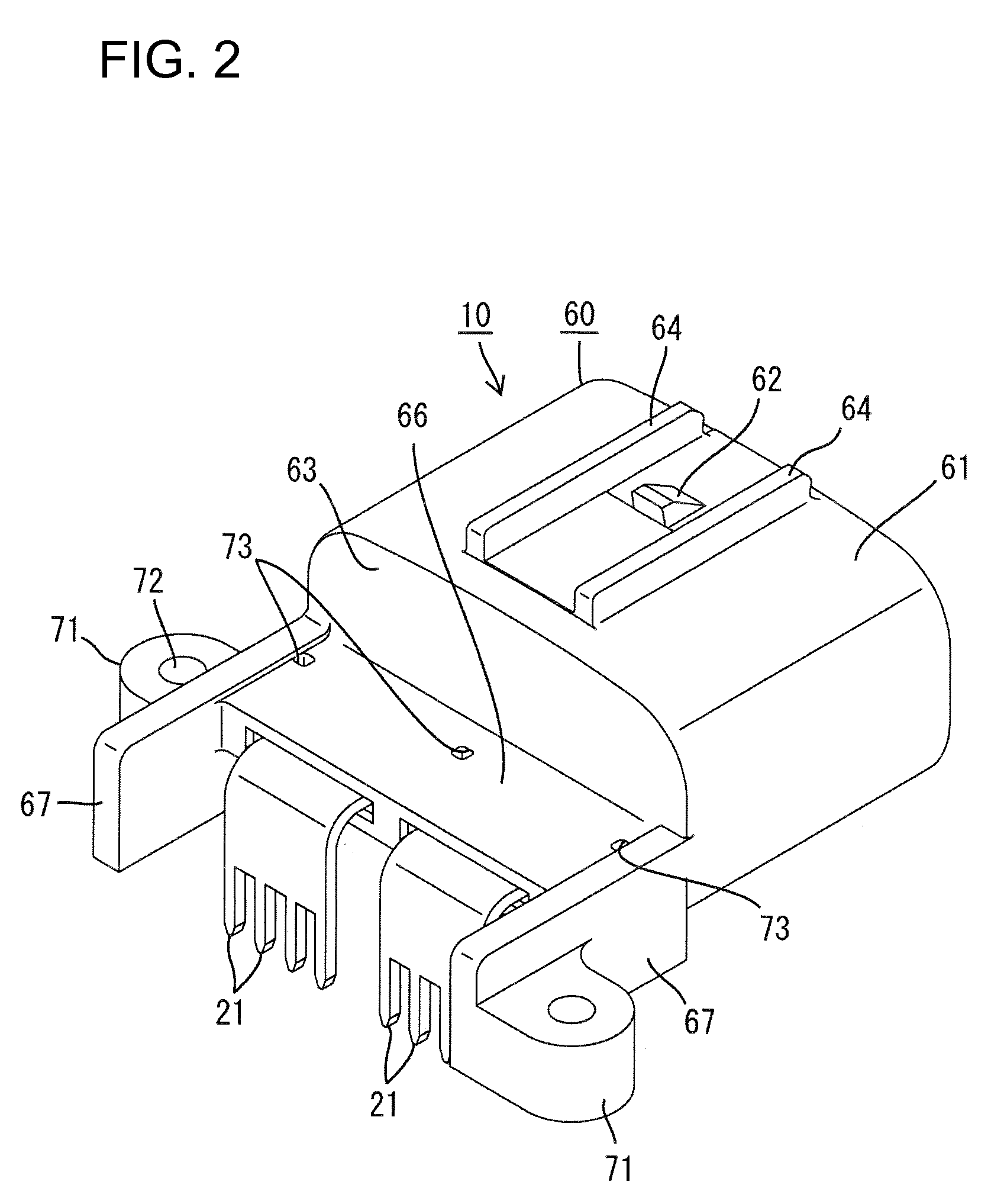
[0018]The housing 60 is made of synthetic resin, and has a wide tubular hood 61 that projects forward from a rear wall 63, as shown in FIGS. 2 and 3. Two side-by-side terminal fittings 20 are press fit into the rear wall 63 of the hood 61. Each terminal fitting 20 is formed from a wide plate-shaped band and is bent approxi...


PUM


Abstract

A housing (60) has two side walls (67) and a covering wall (66) that define a U-shaped channel for covering terminal fittings (20). The housing (60) is mounted on a printed-circuit board (90) so that the U-shaped channel and the circuit board (90) define a bag-shaped space (70). The U-shaped channel of the housing (60) and the circuit board (90) are accommodated in a case (30) so that the bag-shaped space (70) faces down. A potting material (40) then is introduced into the case (30). Air vents (73) are formed through the covering wall (66) and provide communication between the bag-shaped space (70) and an outer surface of the covering wall (66). Thus, air trapped in the bag-shaped space (70) is discharged to the outside through the air vents (73).

Description

BACKGROUND OF THE INVENTION[0001]1. Field of the Invention[0002]The invention relates to a connector for use on a substrate and a method of assembling the connector for use in the substrate.[0003]2. Description of the Related Art[0004]Japanese Patent Application Laid-Open No. 2000-150027 discloses a connector for use on a substrate. The connector has a housing placed on a printed-circuit board and terminal fittings are mounted in the housing. A covering wall and left and right side walls project from the rear of the housing and form a U-shape in a rear view. The terminal fittings are drawn out from the rear of the housing and are bent midway to define an L-shape. The end of the bent portion of each terminal fitting is connected electrically with a conductive path of the printed-circuit board. A rearwardly open bag-shaped space is defined by the covering wall, the side walls, and the printed-circuit board.[0005]The housing can be placed on the printed-circuit board inside a case and ...

Claims


Application Information

Patent Timeline
Patent Type & Authority Applications(United States)
IPC IPC(8): H01R12/16H01R12/00
CPCH01R13/5216H01R13/6272H05K3/284Y10S439/936H05K2201/10446H05K2203/1178H01R12/7047H05K2201/10189
Inventor SAKAKURA, EMI
Owner SUMITOMO WIRING SYST LTD
Why Eureka
Try Eureka