Skin Area Detection Imaging Device

a detection imaging and skin area technology, applied in the field of skin area detection imaging devices, can solve the problems of difficult to obtain a high resolution (or outline shape) of the measured flesh take a long time for the conventional camera to detect the skin area of the object, etc., and achieve the effect of performing in a short tim

Inactive Publication Date: 2008-07-24
FUNAI ELECTRIC CO LTD
View PDF0 Cites 70 Cited by
  • Summary
  • Abstract
  • Description
  • Claims
  • Application Information

AI Technical Summary

Benefits of technology

[0008]An object of the present invention is to provide a skin area detection imaging device for detecting, from an image of an object to be imaged, a skin area of a human body contained in the object illuminated by a light in the near-infrared range, in which the detection can be performed in a short time.
[0010]This skin area detection imaging device detects a skin area of a human body based on two image information obtained by one time imaging operation of the shutter means. Thus, the skin area detection imaging device of the present invention makes it possible to detect the skin area in a short time as compared with the detection device disclosed in Japanese Laid-open Patent Publication 2006-47067, which requires a two-step process to obtain an image of an object illuminated by light of one wavelength, and thereafter obtain an image of the object illuminated by light of the other wavelength.
[0013]Preferably, the two bandpass filters selectively transmit light with different wavelengths in the near-infrared range, respectively, and also transmit light in the visible range. This makes it possible to obtain a normal image e.g. with normal color of the object to be imaged.

Problems solved by technology

This makes it difficult to detect a skin area of a human body in a short time.
Thus, in this conventional camera, it is difficult to obtain a high resolution (or outline shape) of the measured flesh area of the object which is determined by the predetermined number of light measurement areas.
In addition, in principle, it takes a long time for the conventional camera to detect a skin area of the object, because the light measurement areas of the object are required to be sequentially measured for the determination.

Method used


Image

  • Skin Area Detection Imaging Device
  • Skin Area Detection Imaging Device
  • Skin Area Detection Imaging Device

Examples


first embodiment

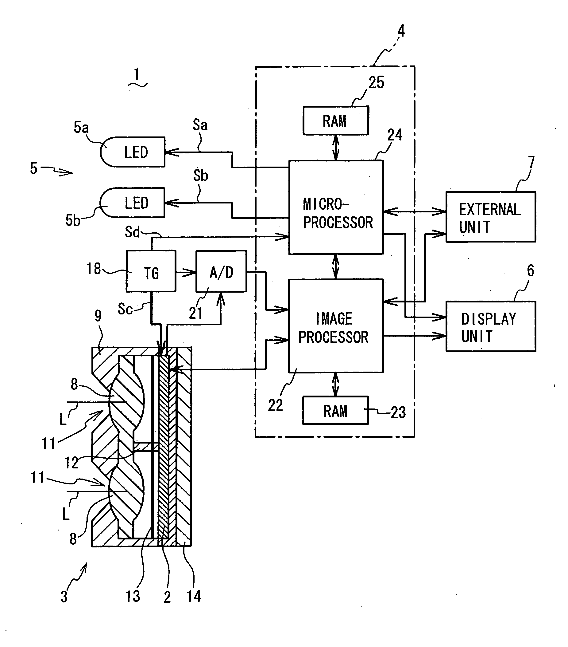
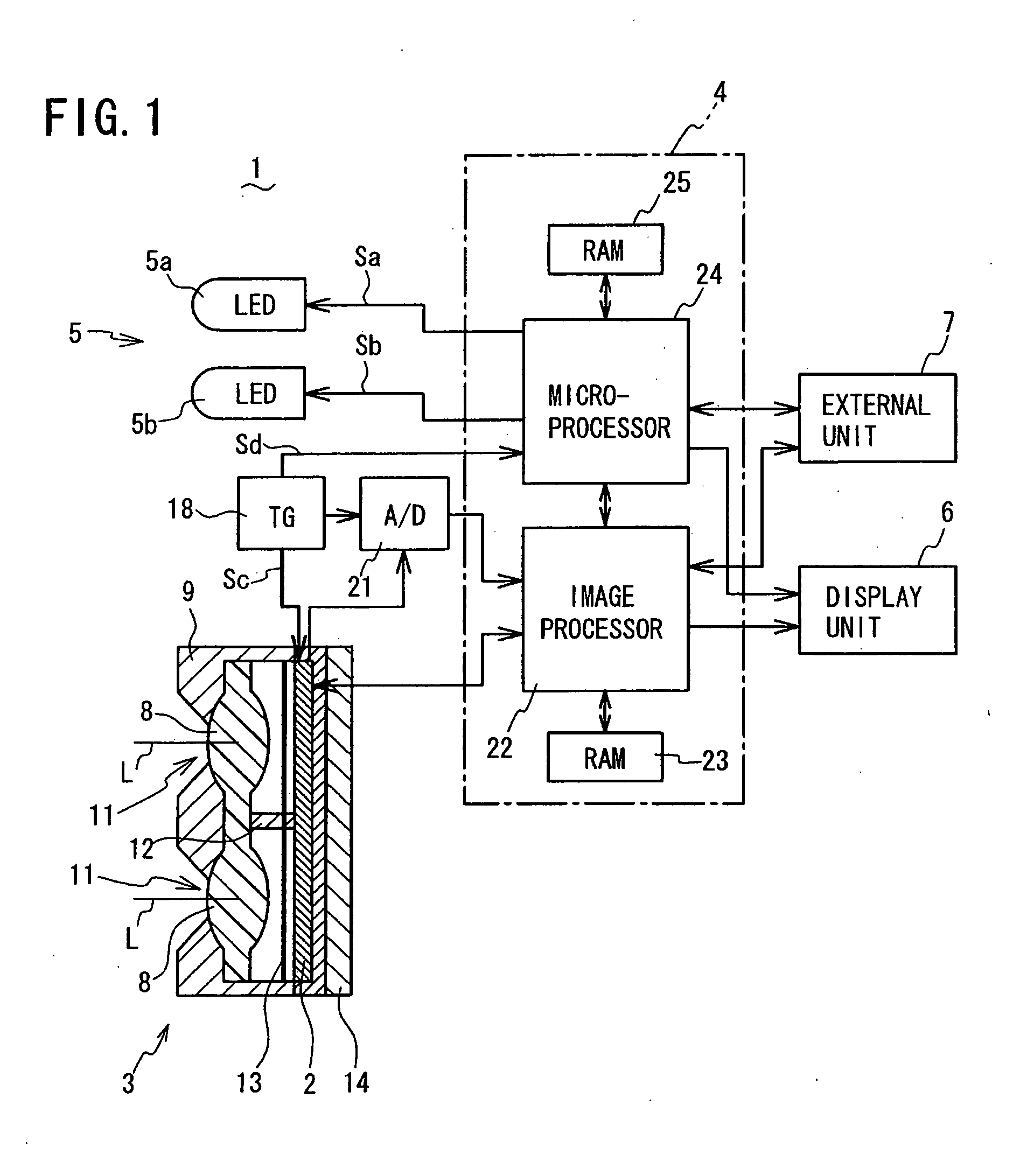
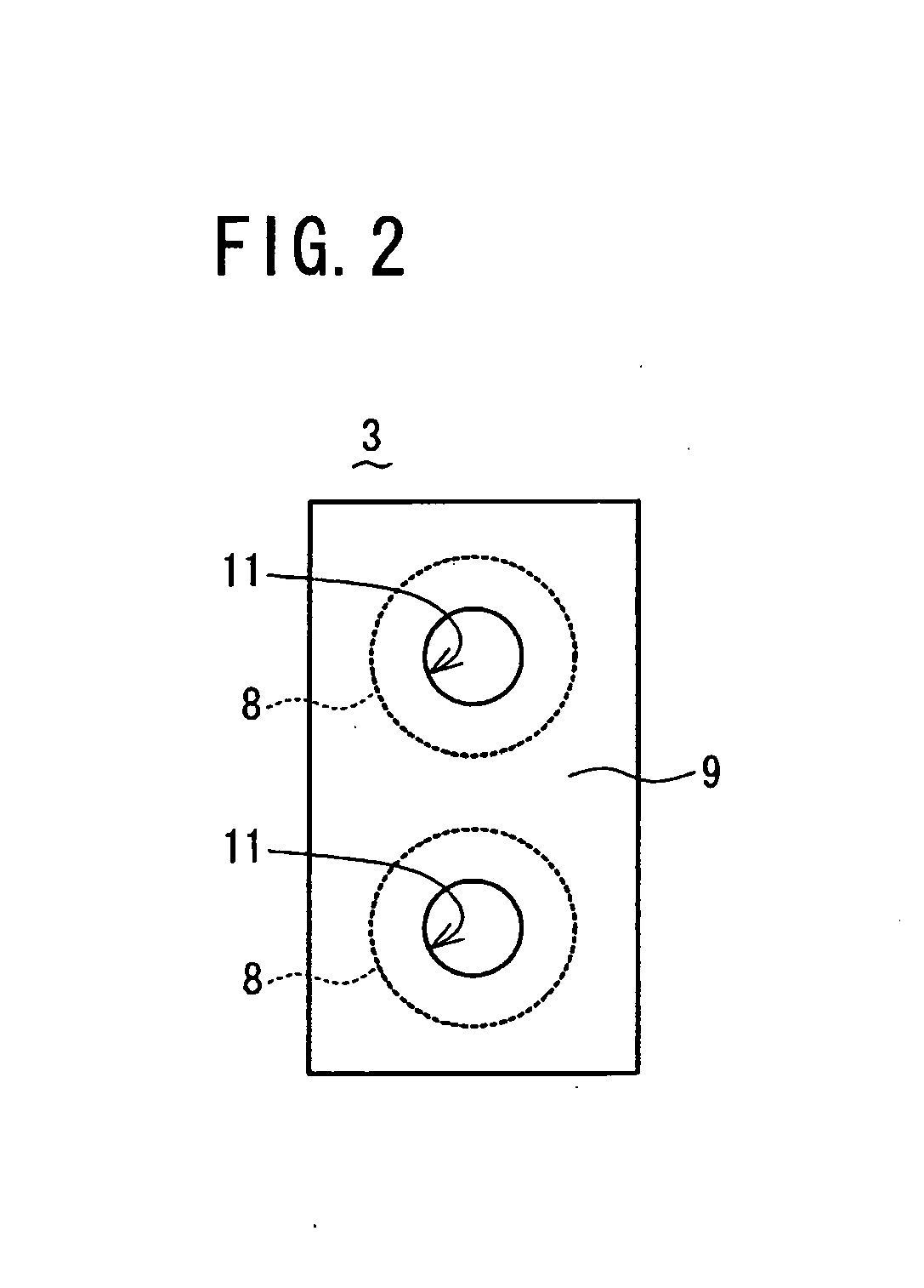
[0031]Referring to FIG. 1 to FIG. 7, a skin area detection imaging device 1 according to a first embodiment of the present invention will be described. FIG. 1 is a schematic block diagram of the skin area detection imaging device 1, also showing a cross-sectional view of an optical lens system 3 contained therein, while FIG. 2 is a schematic front view of the optical lens system 3. FIG. 3 is a schematic front view of a solid-state imaging element 2 with control circuits in block form in the skin area detection imaging device 1. As shown in FIG. 1 to FIG. 3, the skin area detection imaging device 1 comprises an optical lens system 3 for collecting, at a focal point, light from an object to be imaged so as to form two upper and lower images (hereafter referred to as “unit images”) A and B on a solid-state imaging element (photodetector array) 2 placed at the focal point.

[0032]The skin area detection imaging device 1 further comprises: an electronic circuit 4 for electronically process...

second embodiment

[0043]Referring to FIG. 8 to FIG. 10, a skin area detection imaging device 1 according to a second embodiment of the present invention will be described. FIG. 8 is a schematic block diagram of the skin area detection imaging device 1 with bandpass filters 31a and 31b. The skin area detection imaging device 1 of the second embodiment is substantially the same as that of the first embodiment, except that the two LEDs 5a and 5b forming the flash light source 5 in the first embodiment are replaced here by one halogen lamp 5c (which thus also serves as a flash light source 5) to emit wide wavelength light containing the near-infrared range, and that the optical filter 13 in the first embodiment is replaced here by two bandpass filters 31a and 31b to selectively transmit light with two different wavelengths in the near-infrared range, respectively, for two light collection paths 30a and 30b formed by the two optical lenses 8, respectively. These differences between the first and second em...


PUM


Abstract

A skin area detection imaging device for detecting a skin area of a human body as an object comprises: two optical lenses to form two unit images on an imaging element by collecting light from the object illuminated by near-infrared light; a rolling shutter for sequentially reading the unit images; and two LEDs for emitting lights with different wavelengths (850 nm and 940 nm) in the near-infrared range. A microprocessor switches on the two LEDs when reading the two unit images, respectively. The skin area of one read unit image is displayed with brightness different from that of the other unit image based on difference in reflectance to various wavelengths of near-infrared light. The microprocessor compares the two unit images to determine, as a skin area, an area having difference in brightness larger than a predetermined value. This makes it possible to detect the skin area in a short time.

Description

BACKGROUND OF THE INVENTION[0001]1. Field of the Invention[0002]The present invention relates to a skin area detection imaging device, and more particularly to a skin area detection imaging device for detecting, from an image of an object to be imaged, a skin area of a human body contained in the object illuminated by a light in the near-infrared range.[0003]2. Description of the Related Art[0004]When illuminated by a light in the near-infrared range, a skin (flesh) area of a human body (being) has different reflectances to different wavelengths of the light (e.g. about 45% to a light of 850 nm and about 40% to a light of 950 nm). Conventionally, these properties are used e.g. in a monitor camera to detect a human body. For example, Japanese Laid-open Patent Publication 2006-47067 discloses a human body detection device which mounts two light emitting diodes to emit near-infrared lights of two different wavelengths. In this human body detection device, the two light emitting diodes ...

Claims


Application Information

Patent Timeline
Patent Type & Authority Applications(United States)
IPC IPC(8): A61B5/00G06V10/143
CPCG06K9/2018G06K9/00255G06V40/166G06V10/143
Inventor NAKAO, YOSHIZUMIKUGO, KOUICHITOYODA, TAKASHIMASAKI, YASUO
Owner FUNAI ELECTRIC CO LTD
Why Eureka
Try Eureka