
Method for predicting enzyme-catalyzed reactions

Inactive Publication Date: 2008-07-24
TRIAD NAT SECURITY LLC
View PDF3 Cites 13 Cited by
  • Summary
  • Abstract
  • Description
  • Claims
  • Application Information

AI Technical Summary

Benefits of technology

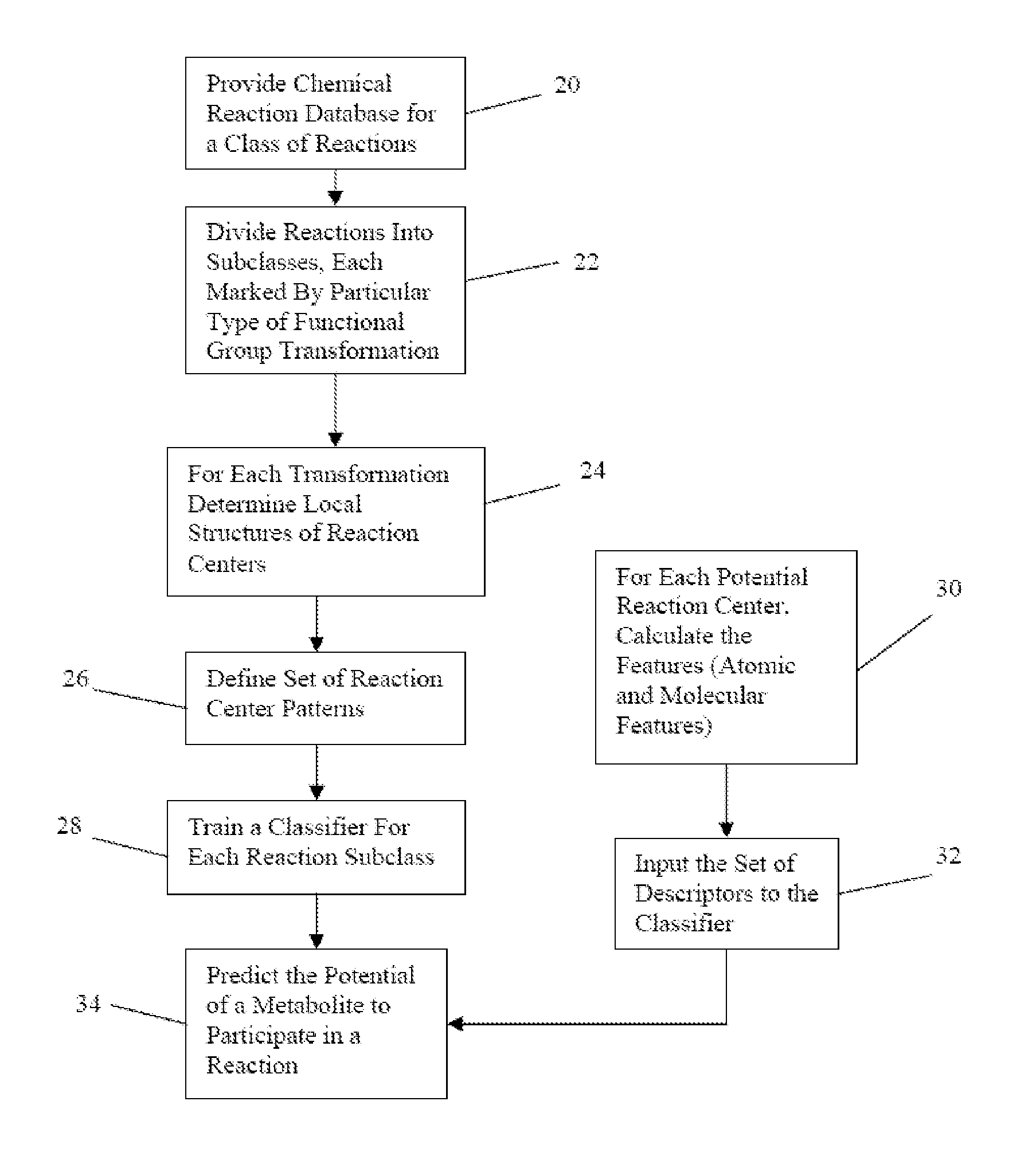
[0013]The invention is an extension of rule-based reaction prediction by incorporating the use of machine learning. For a given chemical structure, potential reaction centers of the biotransformation are identified through molecular structure matching. For each potential reaction center, a set of descriptors selected from chemical properties and features, including atomic features and molecular features, are calculated. Based on a pretrained model using these descriptors, a binary or probability number is given to assess the reactivity potential that the reaction center will perform the given biotransformation. The focus of an illustrative preferred embodiment is on oxidoreductase-catalyzed reactions, which a

Problems solved by technology

Although our knowledge of metabolism is extensive, it is still incomplete.
Systematic and rapid approaches for determining how a newly discovered metabolite is produced and consumed are lacking.
Thus, a present challenge for bioinformatics in support of metabolomics is the development of computational methods that will help place novel metabolites in the context of biochemical pathways efficiently and accurately.
A common problem of systems for rule-based reaction prediction is the number of false positives.
Given a molecule, rule application tends to generate a large number of possible reactions, and a combinatorial explosion occurs if rules are applied iteratively to the products of predicted reactions.
An important challenge is to determine the reactions in which these compounds participate, which can lead to the identification of gene products responsible for novel metabolic pathways.

Method used


Image

  • Method for predicting enzyme-catalyzed reactions
  • Method for predicting enzyme-catalyzed reactions
  • Method for predicting enzyme-catalyzed reactions

Examples


Embodiment Construction

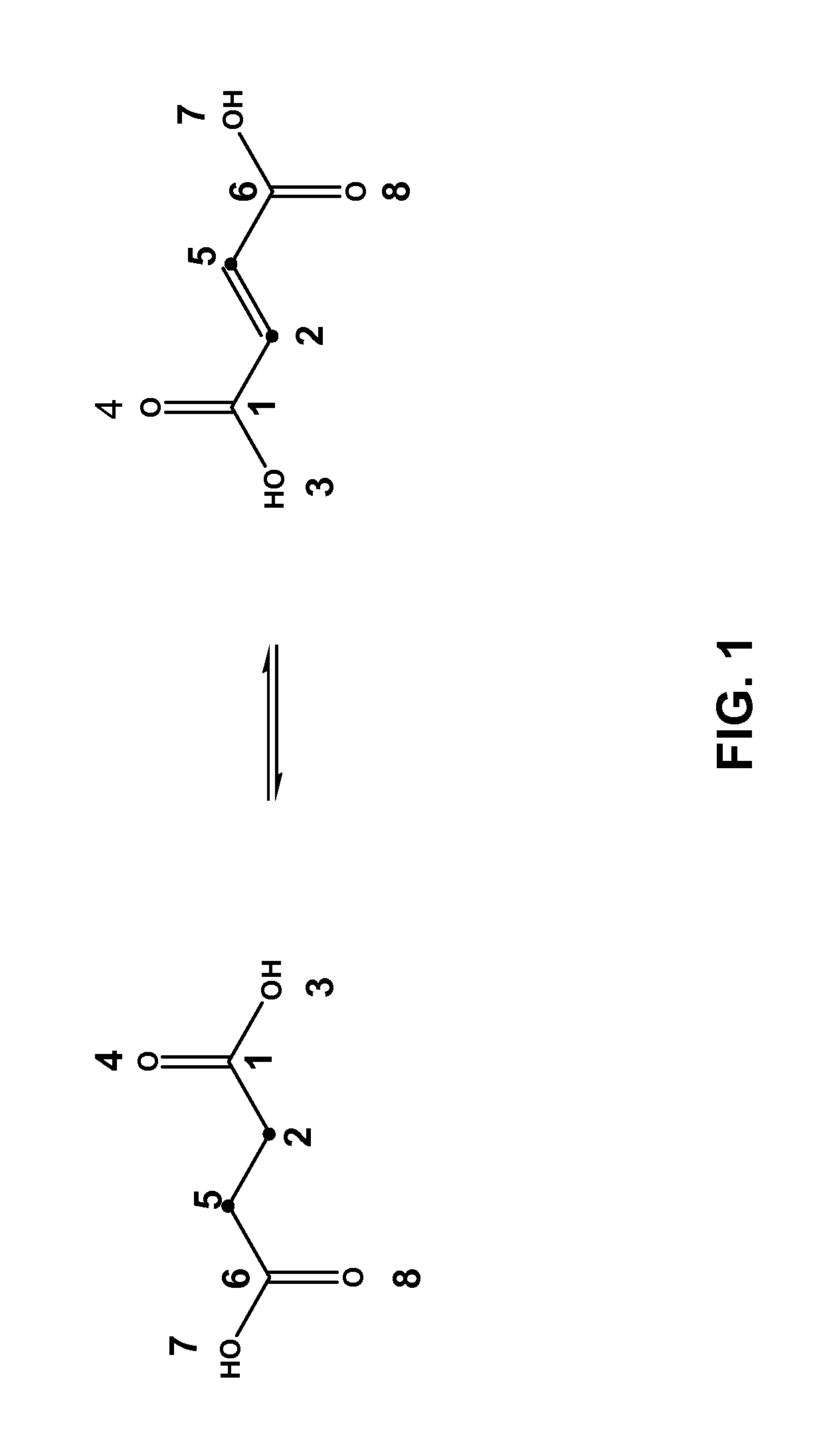
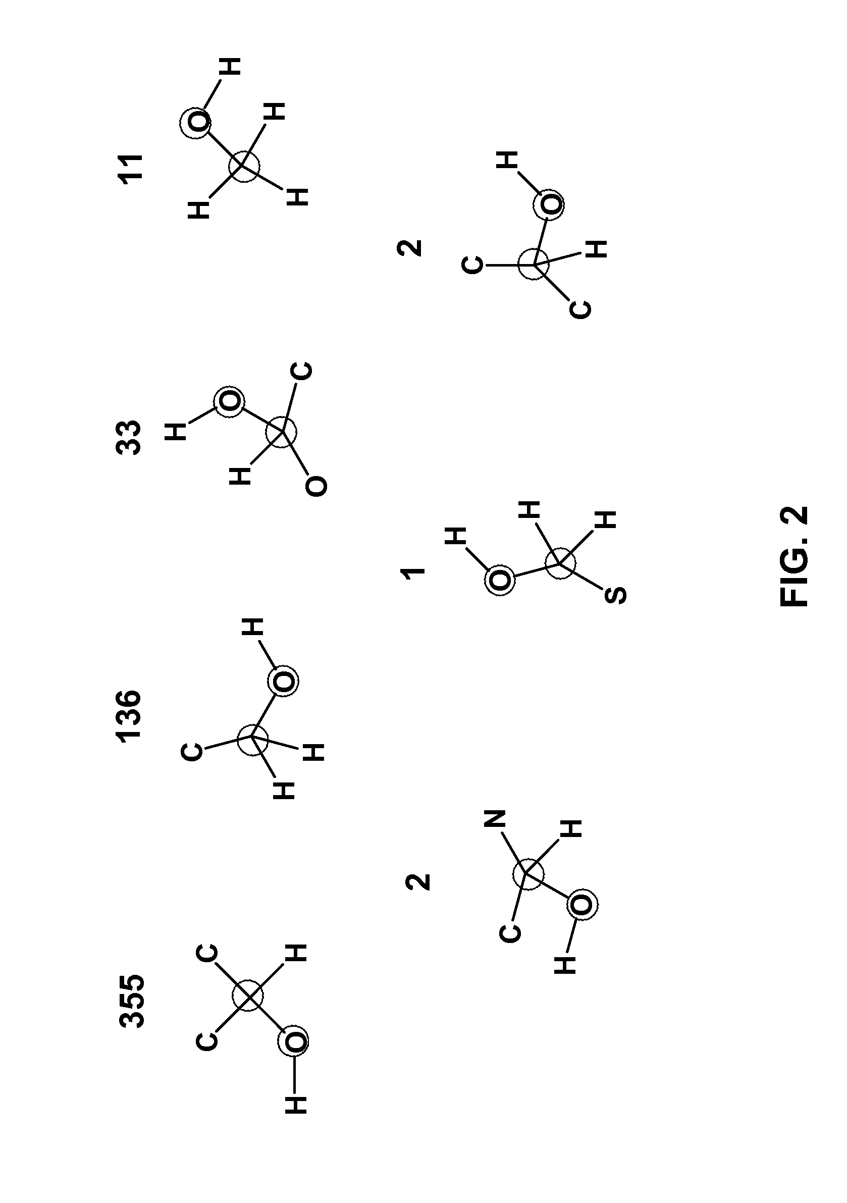
[0031]Referring more specifically to the drawings, for illustrative purposes the present invention is embodied in the data, chemical structures, flowcharts and system diagrams generally shown in FIG. 1 through FIG. 9. It will be appreciated that the method may vary as to sequence and details of the steps and as to specific data used, and the apparatus may vary as to configuration and as to details of the parts, without departing from the basic concepts as disclosed herein.

[0032]The invention applies to the assessment of the reactivity of given metabolites using features to model the atoms in the reaction centers and features to model the whole molecule. Metabolic reactions are represented as biotransformation rules. These rules are generalized from the patterns in reactions. These patterns are not unique to reactants but are widely distributed among metabolites. Using a metabolite database, such as KEGG and MDL's Metabolite®, potential substructures are identified in the metabolites...


PUM


Abstract

The reactivity of given metabolites is assessed using selected empirical atomic properties in the potential reaction center. Metabolic reactions are represented as biotransformation rules. These rules are generalized from the patterns in reactions. These patterns are not unique to reactants but are widely distributed among metabolites. Using a metabolite database, potential substructures are identified in the metabolites for a given biotransformation. These substructures are divided into reactants or non-reactants, depending on whether they participate in the biotransformation or not. Each potential substructure is then modeled using descriptors of the topological and electronic properties of atoms in the potential reaction center; molecular properties can also be used. A Support Vector Machine (SVM) or classifier is trained to classify a potential reactant as a true or false reactant using these properties.

Description

CROSS-REFERENCE TO RELATED APPLICATIONS[0001]This application claims priority from U.S. provisional patent application Ser. No. 60 / 827,362 filed on Sep. 28, 2006, incorporated herein by reference in its entirety.STATEMENT REGARDING FEDERALLY SPONSORED RESEARCH OR DEVELOPMENT[0002]This invention was made with Government support under Contract No. DE-AC52-06NA25396, awarded by the Department of Energy. The Government has certain rights in this invention.INCORPORATION-BY-REFERENCE OF MATERIAL SUBMITTED ON A COMPACT DISC[0003]Not ApplicableNOTICE OF MATERIAL SUBJECT TO COPYRIGHT PROTECTION[0004]A portion of the material in this patent document is subject to copyright protection under the copyright laws of the United States and of other countries. The owner of the copyright rights has no objection to the facsimile reproduction by anyone of the patent document or the patent disclosure, as it appears in the United States Patent and Trademark Office publicly available file or records, but o...

Claims


Application Information

Patent Timeline
IPC IPC(8): G01N33/48
CPCG06F19/702G06F19/707G06F19/704G16C20/10G16C20/30G16C20/70
Inventor HLAVACEK, WILLIAM S.UNKEFER, CLIFFORD J.MU, FANGPINGUNKEFER, PAT J.
Owner TRIAD NAT SECURITY LLC
Learn More