Multilayered bus system

a bus system and multi-layer technology, applied in sustainable buildings, instruments, high-level techniques, etc., can solve the problems of system clock clk stop, conventional multi-layer bus system, and take time to stop or resume operations, so as to achieve reliable and rapid transition to power-saving mode, stop processing of each bus master

Inactive Publication Date: 2008-07-24
LAPIS SEMICON CO LTD
View PDF2 Cites 25 Cited by
  • Summary
  • Abstract
  • Description
  • Claims
  • Application Information

AI Technical Summary

Benefits of technology

[0026]In the present invention, there are provided arbiters each of which outputs a response signal for prohibiting access to each of the bus slaves to each of the bus masters when a power-saving mode is designated by mode setting information supplied from a CPU. It is therefore possible to stop processing of each bus master without depending on software. Since there is provided a clock controller which stops the supply of a system clock, there is no fear that when the power-saving mode is designated, the response signal for prohibiting access is outputted, and an end signal indicating that the respective bus slaves do not perform data transfers for a predetermined period of time is outputted from a monitor, the system clock is stopped during data transfer. Thus, an advantageous effect is brought about in that the transition to the power-saving mode can be carried out reliably and rapidly.

Problems solved by technology

However, the conventional multilayered bus system has the following two problems.
The first problem is that before the transition to the power-saving mode and after the return to the normal operation mode, it is necessary to stop / resume the operations of the bus masters 1b and 1c by software processing based on the CPU 1a, and it will take time to stop or resume the operations actually.
The second problem is that there is a fear that even when the operations of the bus masters 1a through 1c are stopped, the data might remain in the buffers 12a through 12c, and the system clock CLK is stopped while the data of these buffers 12a through 12c are being transferred to the bus slaves 2a and 2b.
When the chip selection signal is given, they are respectively brought into an operating state, thereby increasing power consumption.
On the contrary, the power consumption might increase as a whole.

Method used


Image

  • Multilayered bus system
  • Multilayered bus system
  • Multilayered bus system

Examples


first preferred embodiment

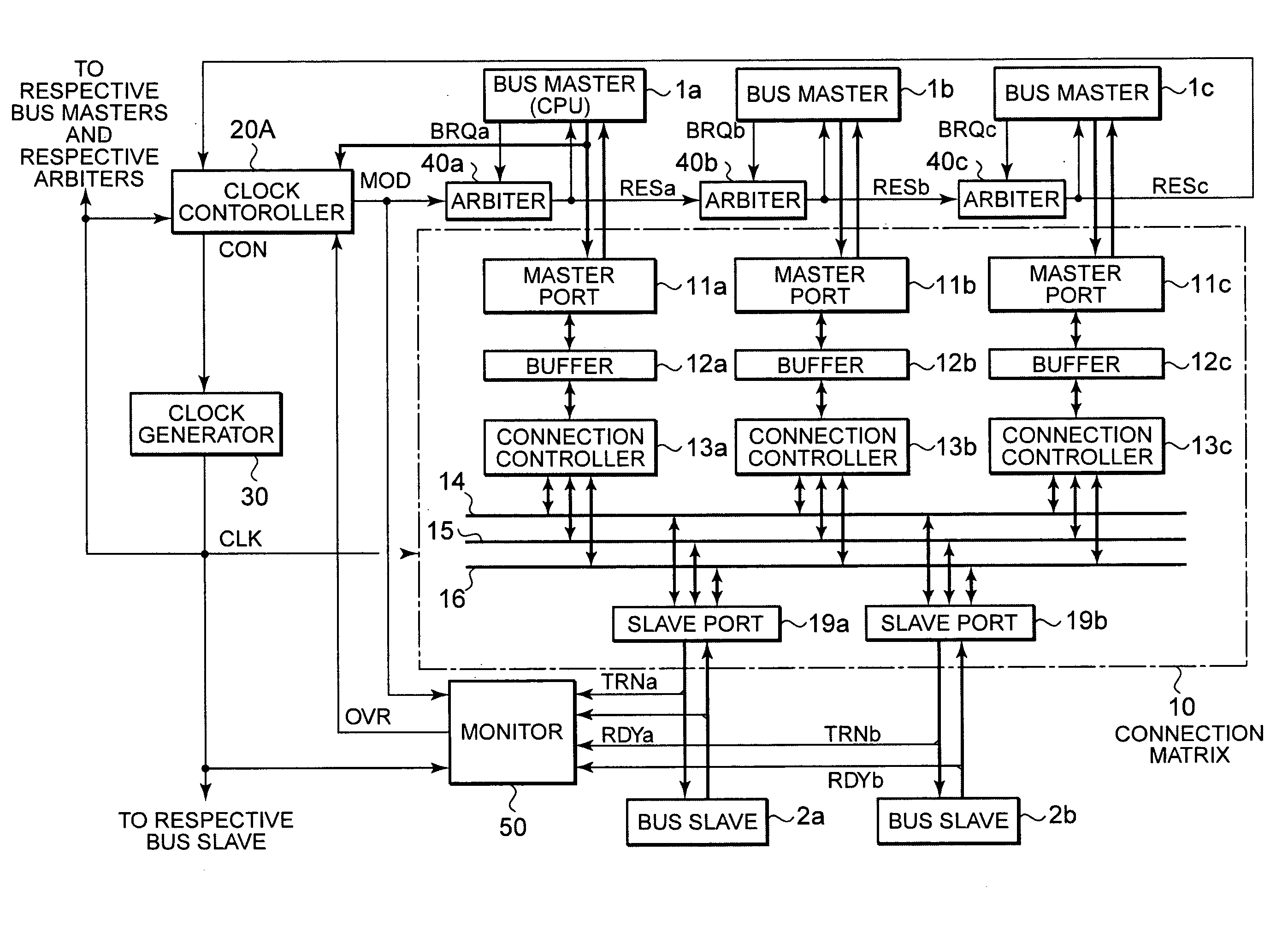
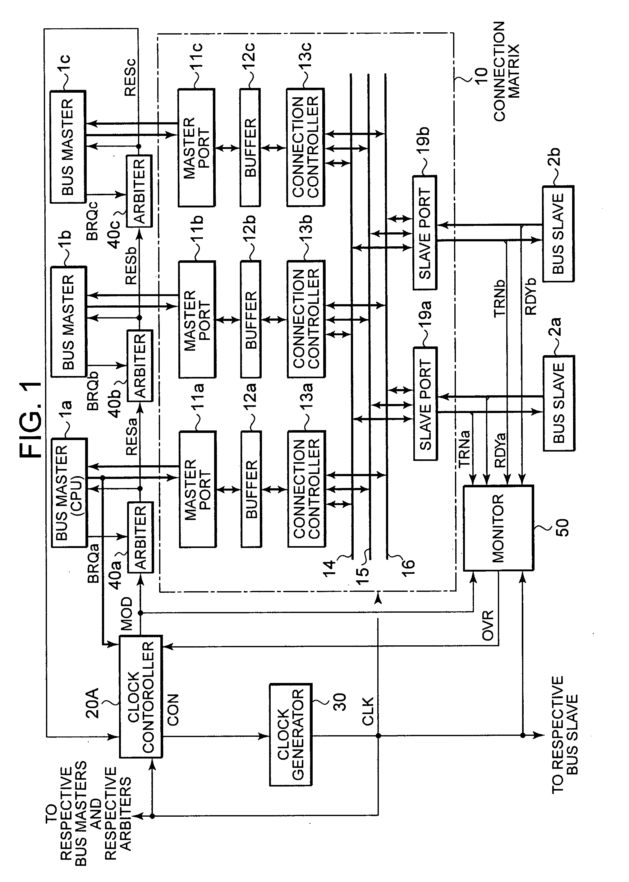
[0034]FIG. 1 is a configuration diagram of a multilayered bus system showing a first embodiment of the present invention. Elements common to those shown in FIG. 2 are given common reference numerals respectively.

[0035]The multilayered bus system is configured so as to connect between a plurality of bus masters each including a CPU and a plurality of bus slaves using a plurality of common buses and perform data transfers in sync with a system clock through a plurality of buffer memories for temporarily retaining data therein. In a manner similar to FIG. 2, the multilayered bus system is equipped with a connection matrix 10 that connects between bus masters 1a, 1b and 1c and bus slaves 2a and 2b according to requests made from the master side, and a clock generator 30 that generates a system clock CLK.

[0036]Incidentally, when the respective bus masters 1a through 1c are connected to the connection matrix 10, they output bus request signals BRQa through BRQC respectively. When the bus ...

second preferred embodiment

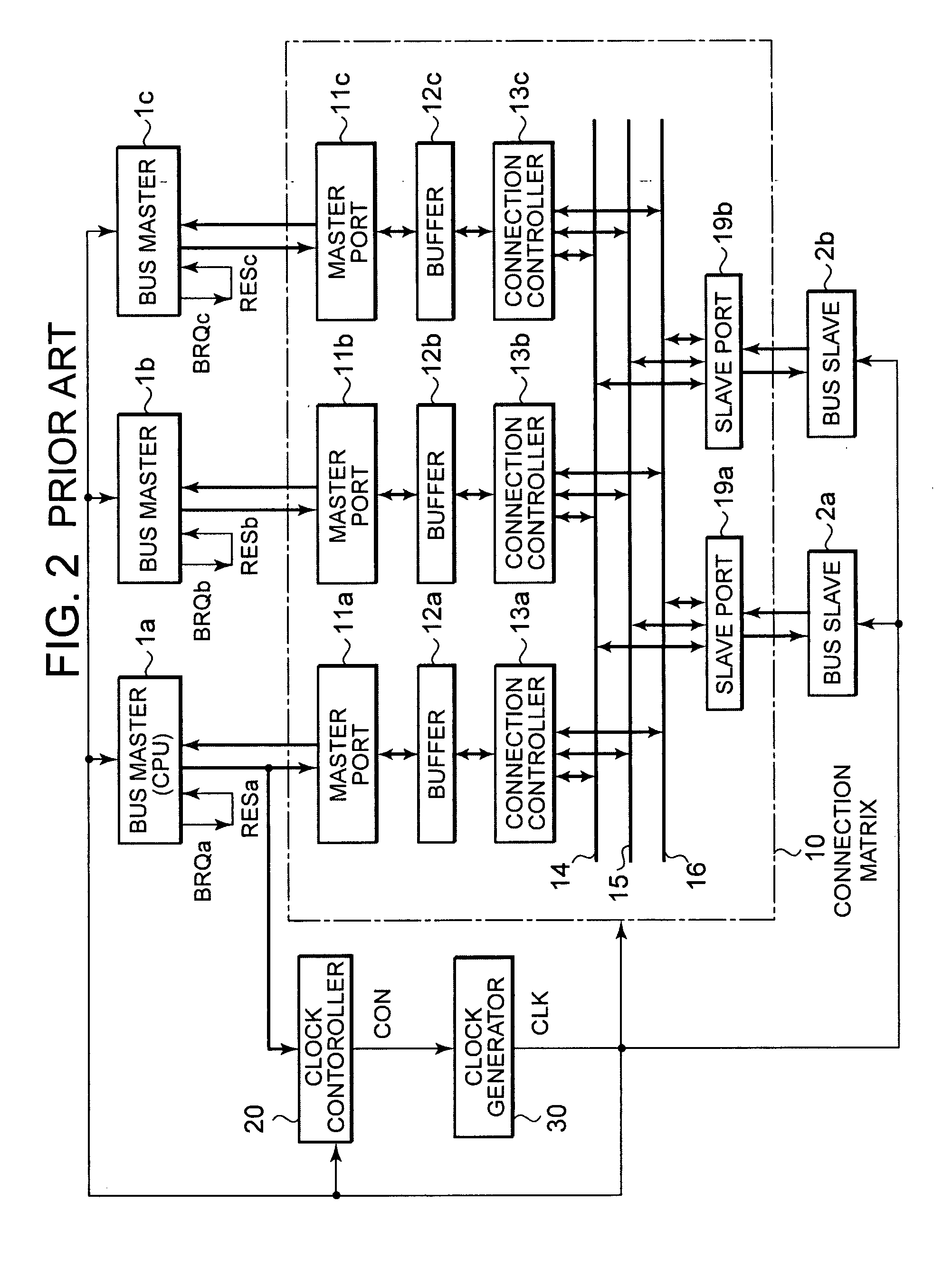
[0057]FIG. 4 is a configuration diagram of a multilayered bus system showing a second embodiment of the present invention. Elements common to those shown in FIG. 1 are given common reference numerals respectively.

[0058]The multilayered bus system is provided with FIFOs 17a through 17c in place of the buffers 12a through 12c shown in FIG. 1, and a monitor constituted of an inverter 56 and a four-input AND 57 as an alternative to the monitor 50.

[0059]The FIFOs 17a through 17c are buffer memories which can be read in a data-written sequence. They are capable of outputting signals indicative of the condition of written data, i.e., indicative of whether the buffers are full or empty. Empty signals EMPa through EMPc indicative of whether the respective FIFOs 17a through 17c are empty are supplied as three input signals of the AND 57. Further, a mode designation signal MOD outputted from a clock controller 20A is inverted by an inverter 56, after which the signal is supplied to the AND 57 ...


PUM


Abstract

The present invention provides a multilayered bus system capable of performing transition to a power-saving mode reliably and rapidly. When a mode designation signal for designating the power-saving mode is outputted from a clock controller in response to mode setting information outputted from a CPU, respective arbiters respectively output response signals for prohibiting access to bus slaves to their corresponding bus masters. When the power-saving mode is designated by the mode designation signal, the response signal for prohibiting access is outputted from the arbiter, and an end signal indicating that the respective bus slaves do not perform data transfers for a predetermined period of time is outputted from a monitor, a control signal for stopping the supply of a system clock is outputted from the clock controller to a clock generator.

Description

BACKGROUND OF THE INVENTION[0001]The present invention relates to a multilayered bus system which connects between a plurality of bus masters and a plurality of bus slaves using a plurality of common buses.[0002]A multilayered bus system is one of such a type that a plurality of common buses are used to connect between a plurality of bus masters and a plurality of bus slaves, thereby avoiding such bus competition as developed in a conventional single-layer bus and making an improvement in throughput.[0003]FIG. 2 is a configuration diagram of a conventional multilayered bus system.[0004]The multilayered bus system is equipped with a connection matrix 10 which connects between bus masters 1a, 1b and 1c and bus slaves 2a and 2b in accordance with requests issued from the master side, a clock generator 30 which generates a system clock CLK, and a clock controller 20 which controls the operation of the clock generator 30.[0005]The connection matrix 10 includes master ports 11a through 11...

Claims


Application Information

Patent Timeline
Patent Type & Authority Applications(United States)
IPC IPC(8): G06F1/32G06F11/30
CPCG06F1/3203Y02B60/32Y02B60/1235G06F1/3253Y02D10/00Y02D30/50
Inventor KAMEGAWA, HIDEKI
Owner LAPIS SEMICON CO LTD
Why Eureka
Try Eureka