Optical fiber cutting device

a cutting device and optical fiber technology, applied in the direction of saw chains, paper/cardboard containers, manufacturing tools, etc., can solve the problems of difficult to properly change the contact area of the blade member with the glass fiber part, the optical fiber rupture surface formed by cleavage is not favorable to the mirror surface, and the operator is burdened between the two, so as to increase the life of the blade member

Active Publication Date: 2008-07-31
SUMITOMO ELECTRIC IND LTD
View PDF4 Cites 10 Cited by
  • Summary
  • Abstract
  • Description
  • Claims
  • Application Information

AI Technical Summary

Benefits of technology

[0018]Exemplary embodiments of the present invention provide an optical fiber cutting device enabled to automatically change the contact area of a blade member with a glass fiber part without imposing a burden onto an operator and to set an amount of rotation, by which the blade member is turned at a time so as to change the contact area, at an optionally small value thereby increasing the lifetime of the blade member.
[0021]Accordingly, the contact area of the blade member with the glass fiber part can automatically be changed without imposing a burden on an operator.(2) An embodiment (hereunder referred to the optical fiber cutting device described in (2)) of the optical fiber cutting device described in (1), further comprises a contact member fixedly provided halfway through a movement path of the blade member. This optical fiber cutting device is featured in that rotation of the blade member is implemented by a contact friction force which is generated by contact between the blade member and the contact member.(3) An embodiment (hereunder referred to the optical fiber cutting device described in (3)) of the optical fiber cutting device described in (2), which is featured in that the blade member includes a feed roller for receiving the contact friction force, and a one-way clutch for transmitting torque of the feed roller to the blade member only duration rotation in one direction of the feed roller.
[0030]With this configuration, a mark provided on the blade member is moved when the blade member is rotated in synchronization with the movement operation of the blade member. Thus, it can easily and visually been checked whether the contact area is properly changed by the rotation of the blade member. This facilitates the adjustment of the amount of rotation of the blade member in synchronization with the movement operation of the blade member.
[0032]Accordingly, the contact area of the blade member with the glass fiber part can automatically be changed without imposing a burden on an operator.

Problems solved by technology

However, in a case where the blade member having been repeatedly used becomes blunt in such a device of the type configured to form a flaw on a surface of a glass fiber part of an optical fiber with the blade member, the fracture surface of the optical fiber formed by rupture caused by a cleavage is not favorable mirror surface.
However, this related-art device has the following problems.
That is, an operation of rotating the blade member so as to change the contact area therebetween is a heavy burden imposed on the operator.
Consequently, it is difficult to properly change the contact area of the blade member with the glass fiber part.
Therefore, the related-art optical fiber cutting device 100 has a problem that it is difficult to lengthen the lifetime of the blade member 107.

Method used


Image

  • Optical fiber cutting device
  • Optical fiber cutting device
  • Optical fiber cutting device

Examples


first embodiment

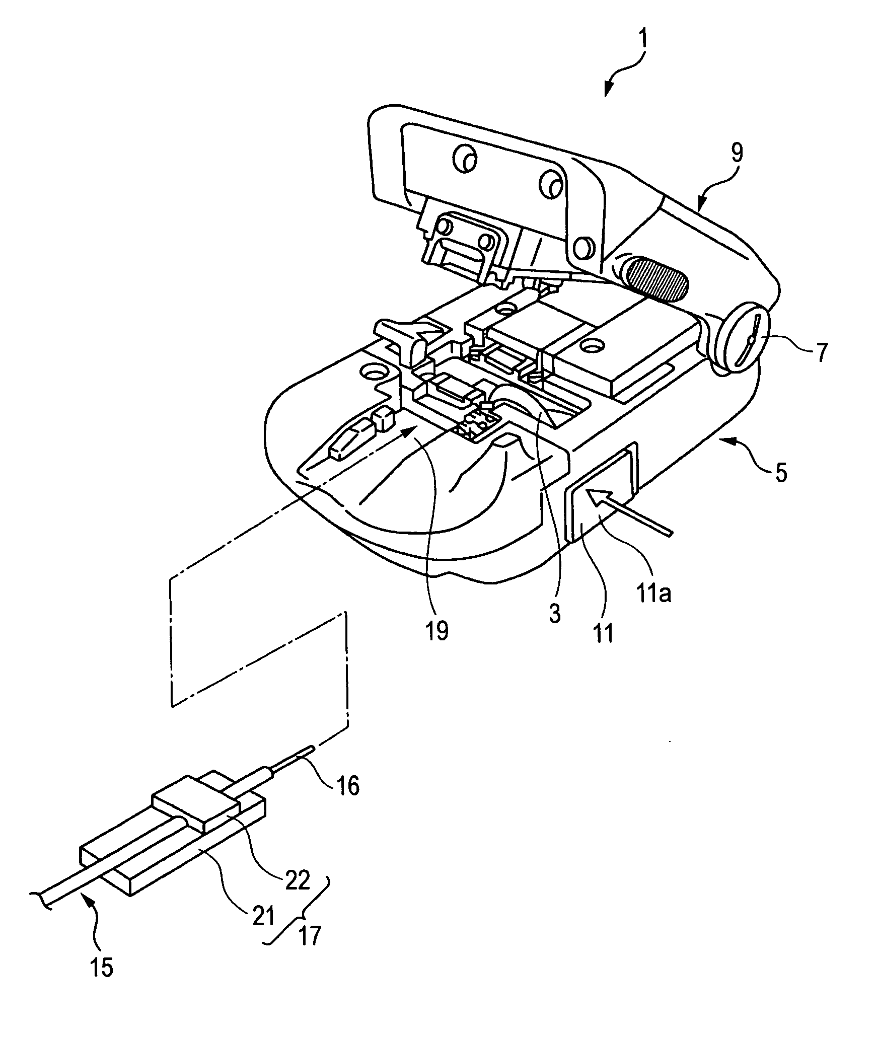
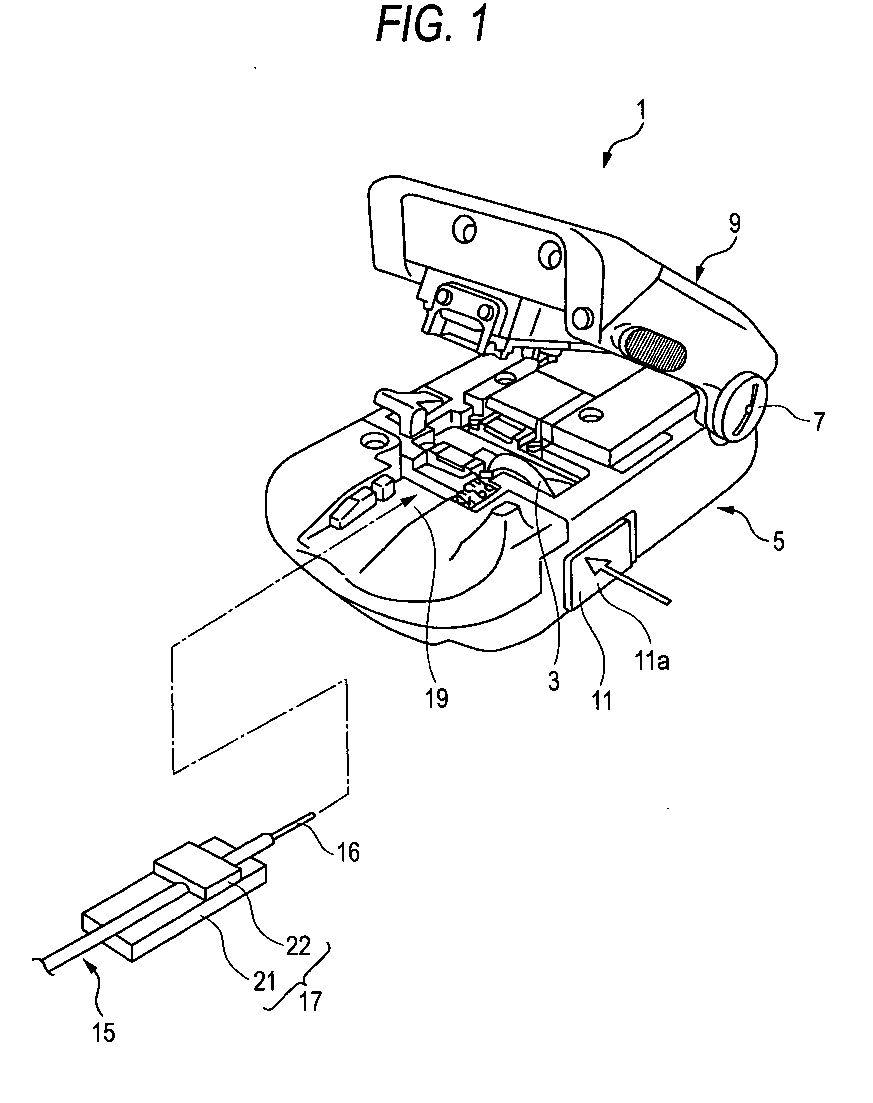
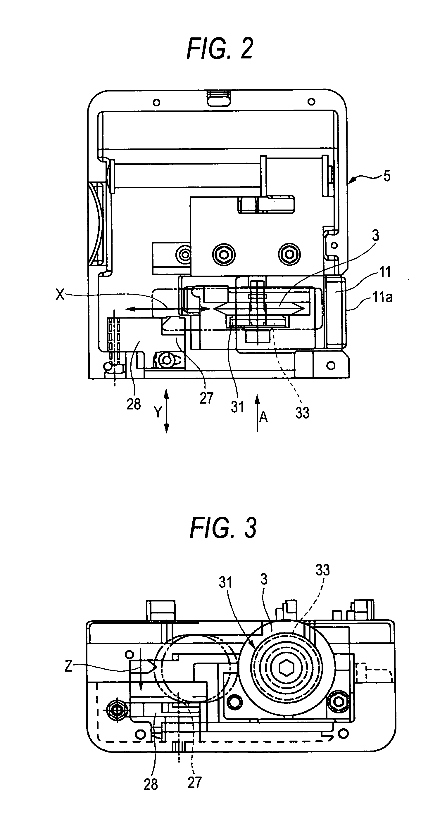
[0048]FIG. 1 is a perspective view schematically illustrating an external appearance of an optical fiber cutting device according to the present invention. FIG. 2 is a plan view illustrating a body of the optical fiber cutting device illustrated in FIG. 1. FIG. 3 is a view taken in the direction of arrow A shown in FIG. 2. FIGS. 4A to 4D are explanatory views illustrating an operation of forming a flaw in a glass fiber part with the blade member shown in FIG. 3.

[0049]As illustrated in FIG. 1, an optical fiber cutting device 1 includes a lower casing 5 which has a disk-like blade member 3, and an upper casing 9 turnably connected to an end of the lower casing 5 through a hinge member 7.

[0050]As illustrated in FIG. 1, a fiber mounting portion 19 for positioning a fiber holder 17, which holds an optical fiber 15, is provided on the top surface of the lower casing 5.

[0051]The fiber holder 17 has a base 21 for supporting the fiber holder 17 from below, and a pressing plate 22 for pressin...

second embodiment

[0088] the rotation of the blade member 3 is implemented in synchronization with the movement thereof, using a gear 37 provided integrally with the blade member 3 and also using an arm member 39 fixedly provided halfway the movement path of the blade member 3 to be brought into surface contact with the gear 37.

[0089]The gear 37 is configured so that concave and convex teeth are continuously formed in a circumferential direction on a ring-like outer peripheral surface. The gear 37 is integrated with the blade member 3 by fitting a projection portion (not shown) protruded from a surface of the gear 37, which faces the blade member 3, into a hole (not shown) formed in an associated surface of the blade member 3.

[0090]The blade member 3 formed integrally with the gear 37 is rotatably mounted in the support frame 11 by a screw 43 passing through the center of the blade member 3. A disk spring 45 is intervened between the gear 37 and the screw 43. The blade member 3 is mounted therein by ...

third embodiment

[0101]FIG. 7 is a plan view illustrating a primary part of a body of the optical fiber cutting device 1B according to the present invention. FIG. 8 is a view taken in the direction of arrow C shown in FIG. 7.

[0102]The optical fiber cutting device 1B according to the third embodiment is an improvement of a structure for fixing the blade member 3 to the gear 37, which has been described in the description of the second embodiment. Other components of the third embodiment are the same as the corresponding components of the second embodiment. Like reference numerals designate like parts and places. The description thereof is omitted.

[0103]In the third embodiment, a circular counterbore 51, into which the gear 37 is fit so as to perform positioning thereof, and a rotation-stop pin 53, which projects to the gear 37 from the bottom surface of the counterbore 51, are provided in a flat part of a surface of the blade member 3. The circular counterbore 51 inhibits the gear 37 fit thereinto fr...


PUM

PropertyMeasurementUnit
pushing forceaaaaaaaaaa
areaaaaaaaaaaa
contact friction forceaaaaaaaaaa

Abstract

An optical fiber cutting device is configured so that a disk-like blade member is moved in a state, in which the blade member is pushed against a glass fiber part of an optical fiber, to form a flaw on a surface of the glass fiber part. The blade member is turned by a feed roller in synchronization with a movement operation of the blade member that rotates by a contact friction force generated when the blade member is put into contact with a contact member fixedly provided halfway a movement path of the blade member.

Description

[0001]This application claims priorities to Japanese Patent Application No. 2007-204172, filed Aug. 6, 2007, and Japanese Patent Application No. 2007-013025, filed Jan. 23, 2007 in the Japanese Patent Office. The priority applications are incorporated by reference in its entirety.TECHNICAL FIELD[0002]The present disclosure relates to an optical fiber cutting device for cutting an optical fiber by forming a flaw on a surface of a glass fiber part of an optical fiber with a disk-like blade member.RELATED ART[0003]A “stress rupture” method is known as a method for cutting a silica-based optical fiber.[0004]This stress rupture method is to first form an initial flaw on a surface of a glass fiber part of an optical fiber by a very hard cutting blade for forming a flaw, which is made of a super-hard alloy or a diamond or the like, and to subsequently apply a bending stress to the glass fiber part so as to cause rupture of the optical fiber, that is, to obtain a mirror surface on a fractur...

Claims


Application Information

Patent Timeline
Patent Type & Authority Applications(United States)
IPC IPC(8): B26D3/08
CPCG02B6/25Y10T225/30Y10T83/768Y10T83/0393Y10T83/929Y10T83/8821
Inventor HONMA, TOSHIHIKO
Owner SUMITOMO ELECTRIC IND LTD
Why Eureka
Try Eureka