
Steam generator nozzle dam and method for installing and removing steam generator nozzle dam

Inactive Publication Date: 2008-07-31
CURTISS WRIGHT FLOW CONTROL SERVICE
View PDF7 Cites 12 Cited by
  • Summary
  • Abstract
  • Description
  • Claims
  • Application Information

AI Technical Summary

Benefits of technology

[0013]A center locking mechanism may be provided for locking the two disc segments together in an unfolded state of the nozzle dam. Further, a rotation limiting mechanism may be provided on the nozzle dam to prevent over-rotation of the nozzle dam assembly in the attachment ring. In addition, a locking mechanism may be provided for locking the nozzle dam into the attachment ring. The locking mechanism may comprise a locking pin, a locking tab, or the like.

Problems solved by technology

Accordingly, these prior art nozzle dams were limited in terms of placement position in the nozzle, attachment points and supports, unknown sealing surfaces of the nozzles, and limited manway openings.
Further, such prior art nozzle dam installation technicians are subject to radiation exposure level limitations.
These constraints resulted in nozzle dams that were large in size, heavy in weight, difficult and time consuming to install and remove, had unknown sealing surfaces, expensive to manufacture, comprised of multiple moving components such as structural bolts, pins or other locking mechanisms each of which had the potential for failure, and not readily adapted for remote installation or removal.

Method used


Image

  • Steam generator nozzle dam and method for installing and removing steam generator nozzle dam
  • Steam generator nozzle dam and method for installing and removing steam generator nozzle dam
  • Steam generator nozzle dam and method for installing and removing steam generator nozzle dam

Examples


Embodiment Construction

[0069]The ensuing detailed description provides exemplary embodiments only, and is not intended to limit the scope, applicability, or configuration of the invention. Rather, the ensuing detailed description of the exemplary embodiments will provide those skilled in the art with an enabling description for implementing an embodiment of the invention. It should be understood that various changes may be made in the function and arrangement of elements without departing from the spirit and scope of the invention as set forth in the appended claims.

[0070]The present invention relates to improved nozzle dams for hot and cold legs of a steam generator, as well as methods for installing and removing such an improved nozzle dams.

[0071]As shown in FIGS. 5-19B, the present invention includes various example aspects and embodiments of a nozzle dam system that includes a nozzle dam assembly and a nozzle dam attachment ring designed to accept the nozzle dam assembly. In the example embodiment sho...


PUM


Abstract

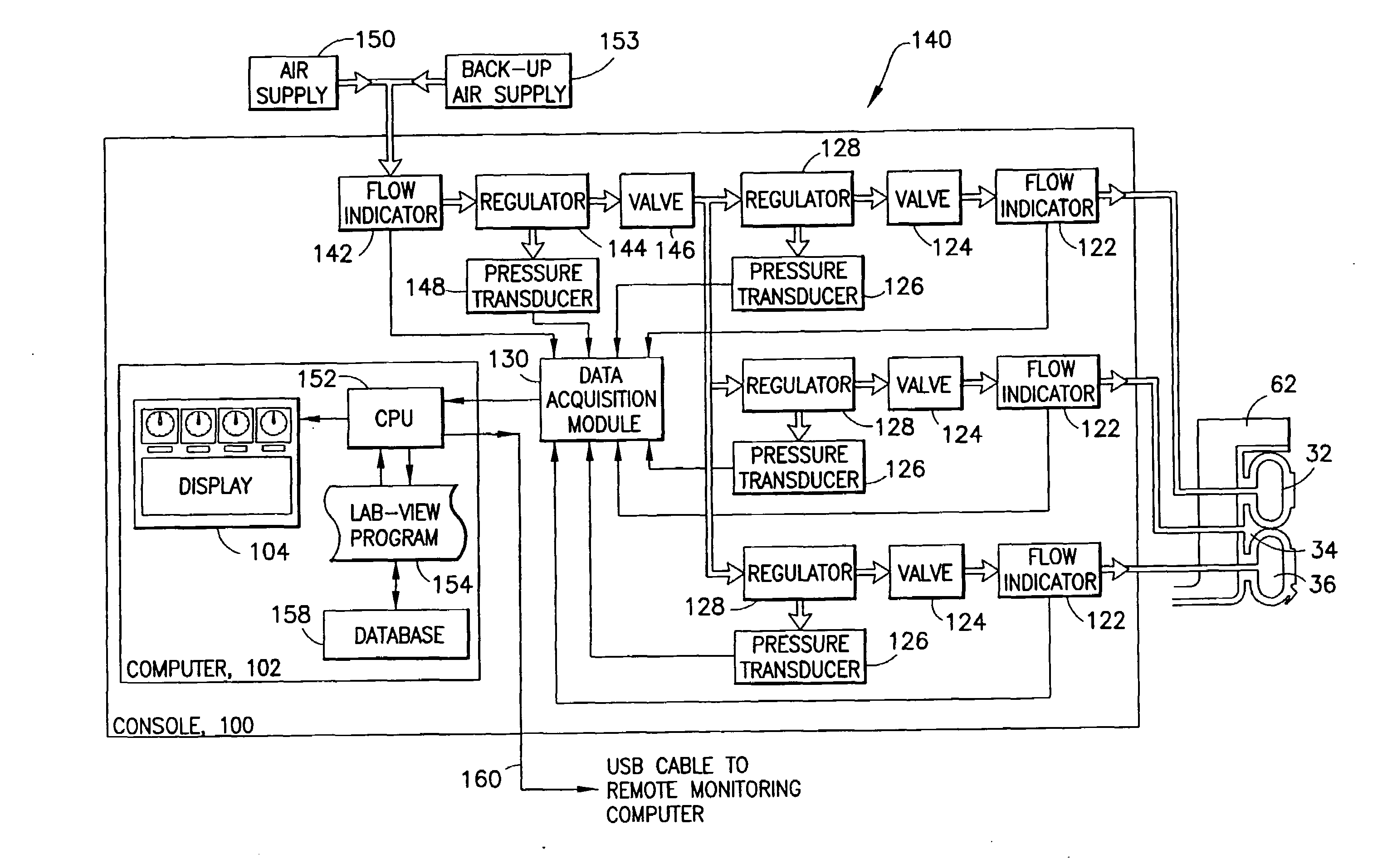
The present invention includes an apparatus for watertight sealing of a steam generator nozzle and methods for installing the apparatus. The apparatus comprises a nozzle dam, a nozzle dam attachment ring, and a seal. The attachment ring is provided in an interior of the nozzle and has a plurality of retaining tabs and a nozzle dam landing. The nozzle dam is adapted for insertion into the attachment ring and abutment against the nozzle dam landing. The nozzle dam has a plurality of radial protrusions adapted to interlock with the retaining tabs for fixing the nozzle dam in the attachment ring upon rotation of the nozzle dam in the attachment ring. The seal covers at least one side of the nozzle dam for effecting a seal between the nozzle dam and the attachment ring. The present invention also provides methods and apparatus for the pressurization and control of nozzle dam seals.

Description

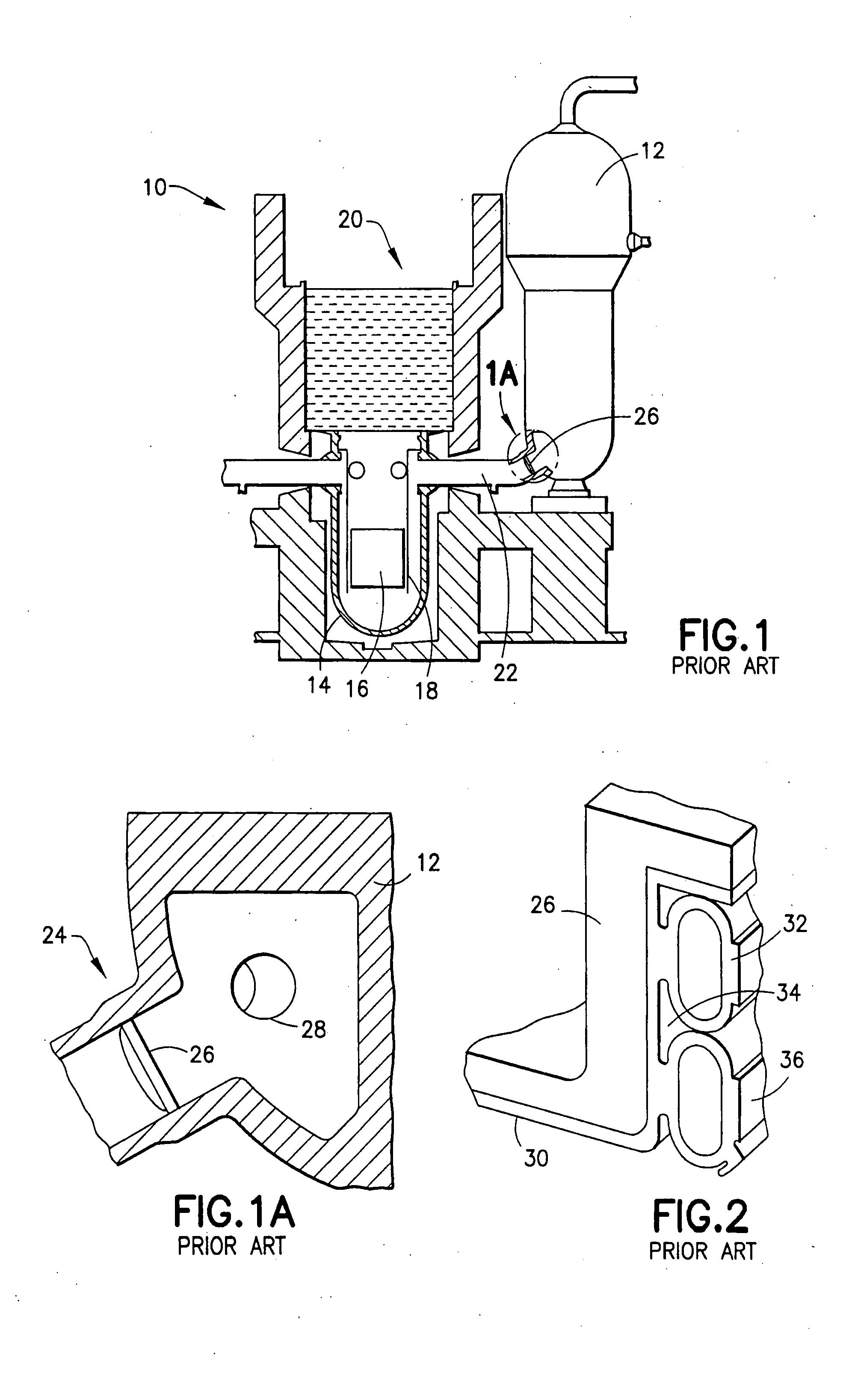
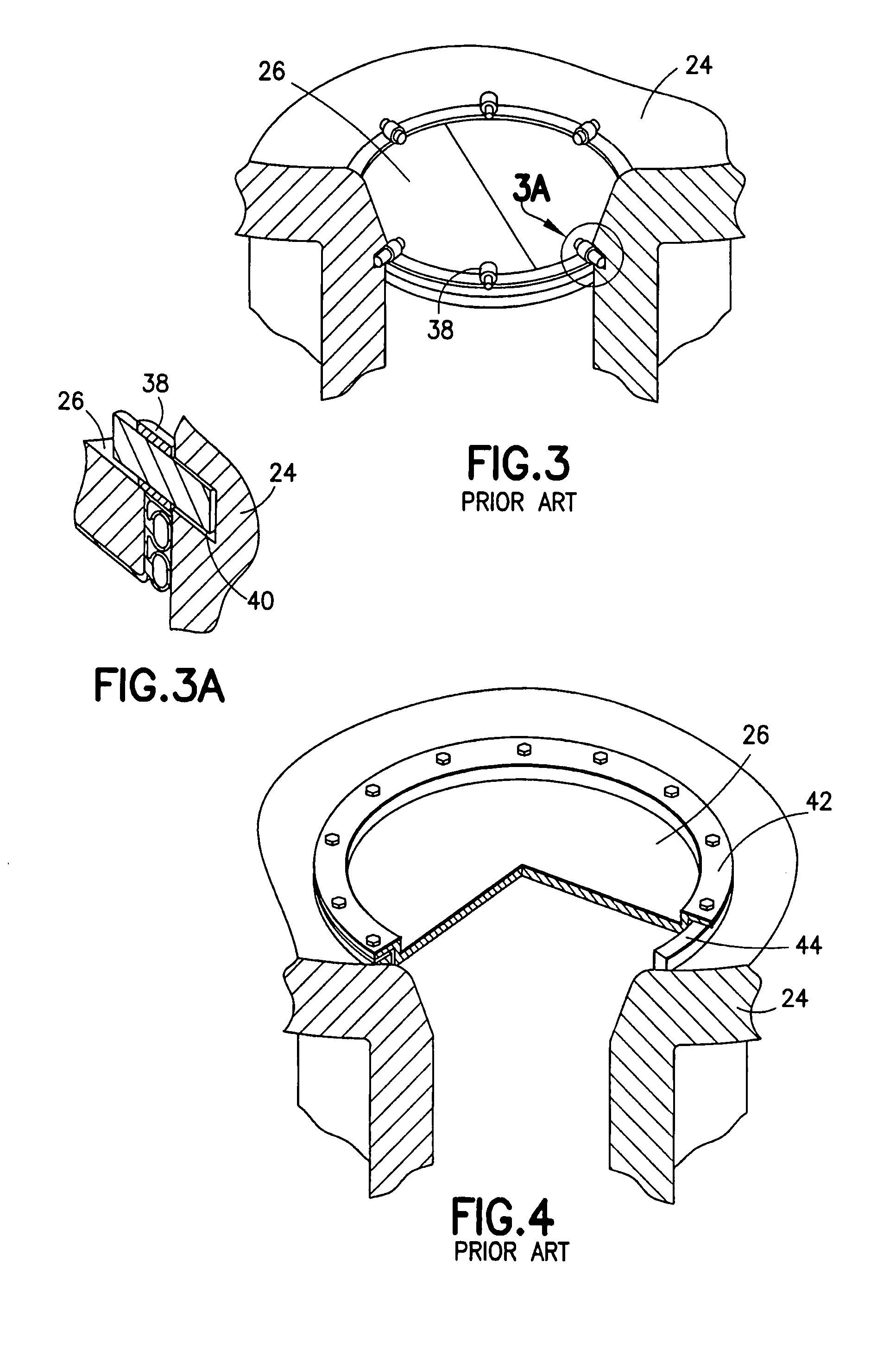
[0001]This application claims the benefit of U.S. provisional patent application No. 60 / 873,726 filed on Dec. 7, 2006 and U.S. provisional patent application No. 60 / 860,538 filed on Nov. 21, 2006, each of which is incorporated herein by reference in their entirety and for all purposes.BACKGROUND OF THE INVENTION[0002]The present invention relates generally to the field of steam generators used in nuclear power plants. More specifically, the present invention relates to improved nozzle dams for hot and cold legs of a steam generator, as well as methods for installing and removing such improved nozzle dams. The present invention also includes methods and apparatus for the pressurization and control of steam generator nozzle dam seals.[0003]Nuclear power plants are routinely shut down for refueling, maintenance, inspection, and testing. FIG. 1 shows a simplified diagram of a typical nuclear power plant 10 which includes a steam generator 12, a reactor pressure vessel 14 holding a react...

Claims


Application Information

Patent Timeline
IPC IPC(8): F22B37/22
CPCF22B37/42F22B37/002
Inventor EVANS, CLIFFDALTON, MARK W.
Owner CURTISS WRIGHT FLOW CONTROL SERVICE
Learn More