Liquid collection system and related methods

a collection system and liquid technology, applied in the direction of liquid transferring devices, suction drainage containers, instruments, etc., can solve the problems of increasing the risk of potentially hazardous waste exposure of clinicians, insufficient information about the content and amount of liquid being collected, and inconvenient operation, so as to reduce the risk of exposure of medical personnel, improve labor efficiency, and improve safety and convenien

Active Publication Date: 2008-07-31
ALLEGIANCE CORP
View PDF17 Cites 40 Cited by
  • Summary
  • Abstract
  • Description
  • Claims
  • Application Information

AI Technical Summary

Benefits of technology

[0006]Therefore, various exemplary embodiments of the invention may provide a liquid collection system that utilizes multiple storage chambers to improve labor efficiency, safety, and convenience of the medical personnel participating in a liquid collection process. For example, the multiple storage chambers may provide a clean collection interface that may reduce the need for frequent disposal processes, thereby reducing the medical personnel's risk of exposure to potentially hazardous waste.

Problems solved by technology

This process can be labor intensive and time consuming.
Furthermore, since this process is performed every time following each medical procedure, it may increase the clinicians' risk of exposure to potentially hazardous waste.
Such a system, however, cannot provide adequate information about the content and amount of liquid being collected during a medical procedure, since the liquid being collected directly flows into the large container and is mixed with the previously collected waste.
Thus, physicians and clinicians participating in the procedure may not be able to make a quick and simple visual assessment of the contents and amount of liquid being collected to determine, for example, the amount of blood loss or the composition of the liquid, which may be critical in certain types of medical procedures.

Method used


Image

  • Liquid collection system and related methods
  • Liquid collection system and related methods
  • Liquid collection system and related methods

Examples


Embodiment Construction

[0053]Reference will now be made in detail to exemplary embodiments consistent with the present invention, examples of which are illustrated in the accompanying drawings. Wherever possible, the same reference numbers will be used throughout the drawings to refer to the same or like parts.

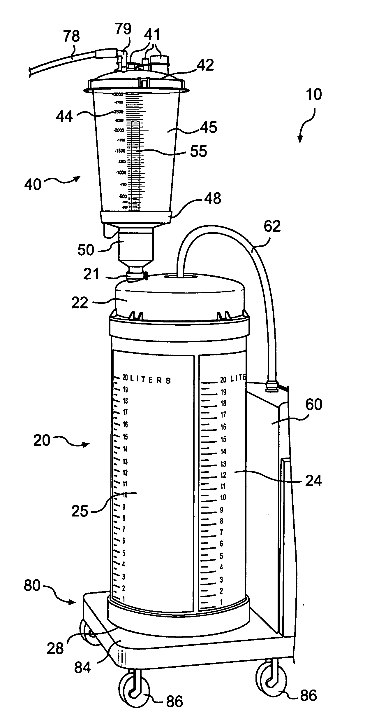
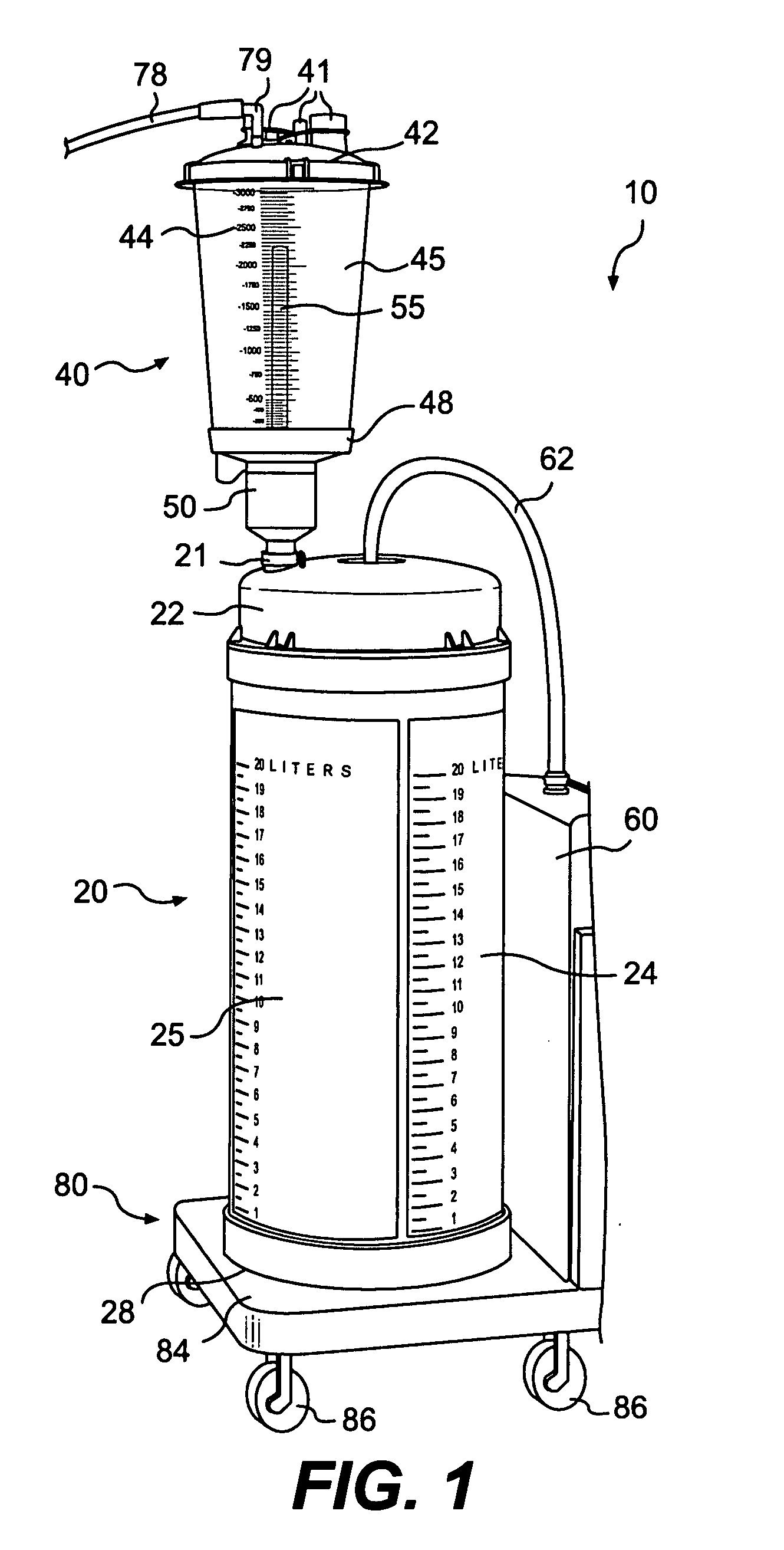
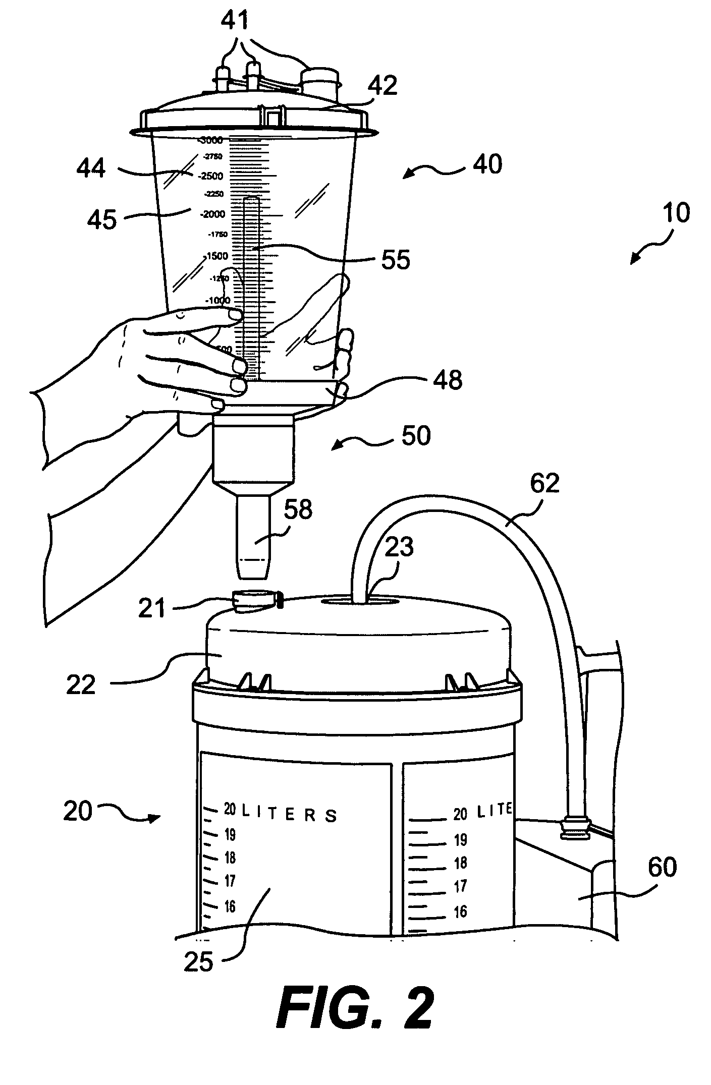
[0054]FIGS. 1 and 2 show a multi-chamber liquid collection system 10, according to an exemplary embodiment of the invention. The system 10 may comprise a first chamber 20, a second chamber 40, and a suitable suction source 60. The suction source 60, which may be a portable unit, may comprise a suction pump or compressor to generate a negative pressure (e.g., vacuum) in the first and second chambers 20, 40. The negative pressure may be used to draw liquid into the collection system 10.

[0055]The term “liquid,” as used herein, is not merely referring to a state of matter as defined in the thermodynamic and / or fluid mechanics art. Instead, the term “liquid” includes any solid particles that may incident...


PUM


Abstract

Various embodiments of a fluid collection system having multiple storage chambers are disclosed. In an exemplary embodiment, the system may include a first chamber in fluid communication with a suction source and a second chamber in fluid communication with the first chamber. The second chamber may have a volume less than a volume of the first chamber. The second chamber may also comprise an inlet port for connecting to an external tube. The system may be configured to selectively drain liquid from the second chamber into the first chamber.

Description

FIELD OF THE INVENTION[0001]Embodiments of the present invention relate generally to fluid collection systems and related methods. More specifically, particular embodiments of the invention relate to a liquid collection system having multiple storage chambers and related methods of use.DESCRIPTION OF RELATED ART[0002]Hospital operating rooms and other healthcare facilities generate a large volume of liquid waste, which may include irrigation liquids and secretions removed from patient's body (e.g., blood and other bodily liquids). One study shows that a typical operating room generates about two tons of liquid waste each month. Such liquid waste is considered infectious medical waste and must be disposed of in accordance with stringent safety standards established by federal and state regulations.[0003]To collect and dispose such liquid waste, suction canisters are typically used in hospital operating rooms and other healthcare facilities. A suction canister is a temporary storage c...

Claims


Application Information

Patent Timeline
Patent Type & Authority Applications(United States)
IPC IPC(8): B67D5/60B67D5/30G01F11/00B67D7/78B67D7/30
CPCA61M1/0001A61M1/0005A61M1/0017G01F23/02G01F23/0053A61M1/631A61M1/604
Inventor MICHAELS, THOMAS L.JOHNSON, RUSS A.THOMAS, JEANNIE
Owner ALLEGIANCE CORP
Why Eureka
Try Eureka