Model railroad track switch actuator assembly

Inactive Publication Date: 2008-07-31
HEMPHILL LEWIS
View PDF5 Cites 0 Cited by
  • Summary
  • Abstract
  • Description
  • Claims
  • Application Information

AI Technical Summary

Benefits of technology

[0006]The present invention satisfies the aforementioned need by providing a track switch actuator which has the advantages of slow, smooth realistic operation, small package size that permits installation directly to the bottom of a track switch and unobtrusive, simple design which

Problems solved by technology

1) It obviates “under the table” installation w

Method used


Image

  • Model railroad track switch actuator assembly
  • Model railroad track switch actuator assembly
  • Model railroad track switch actuator assembly

Examples


Example

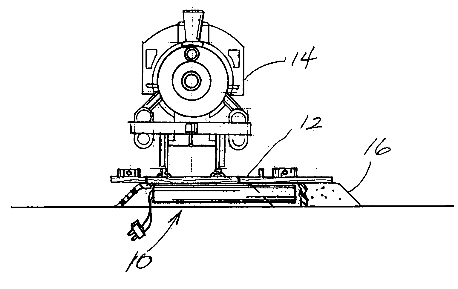
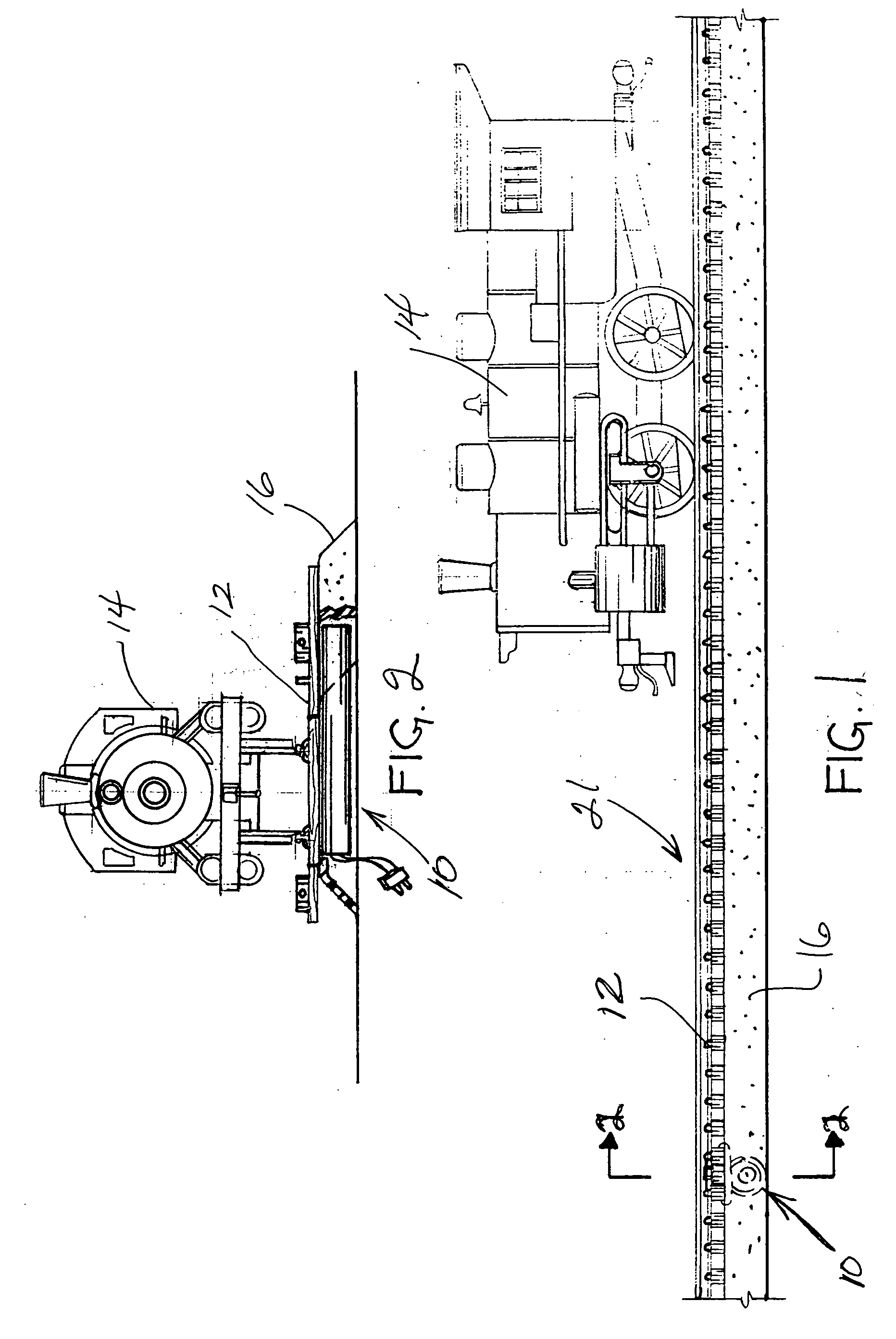
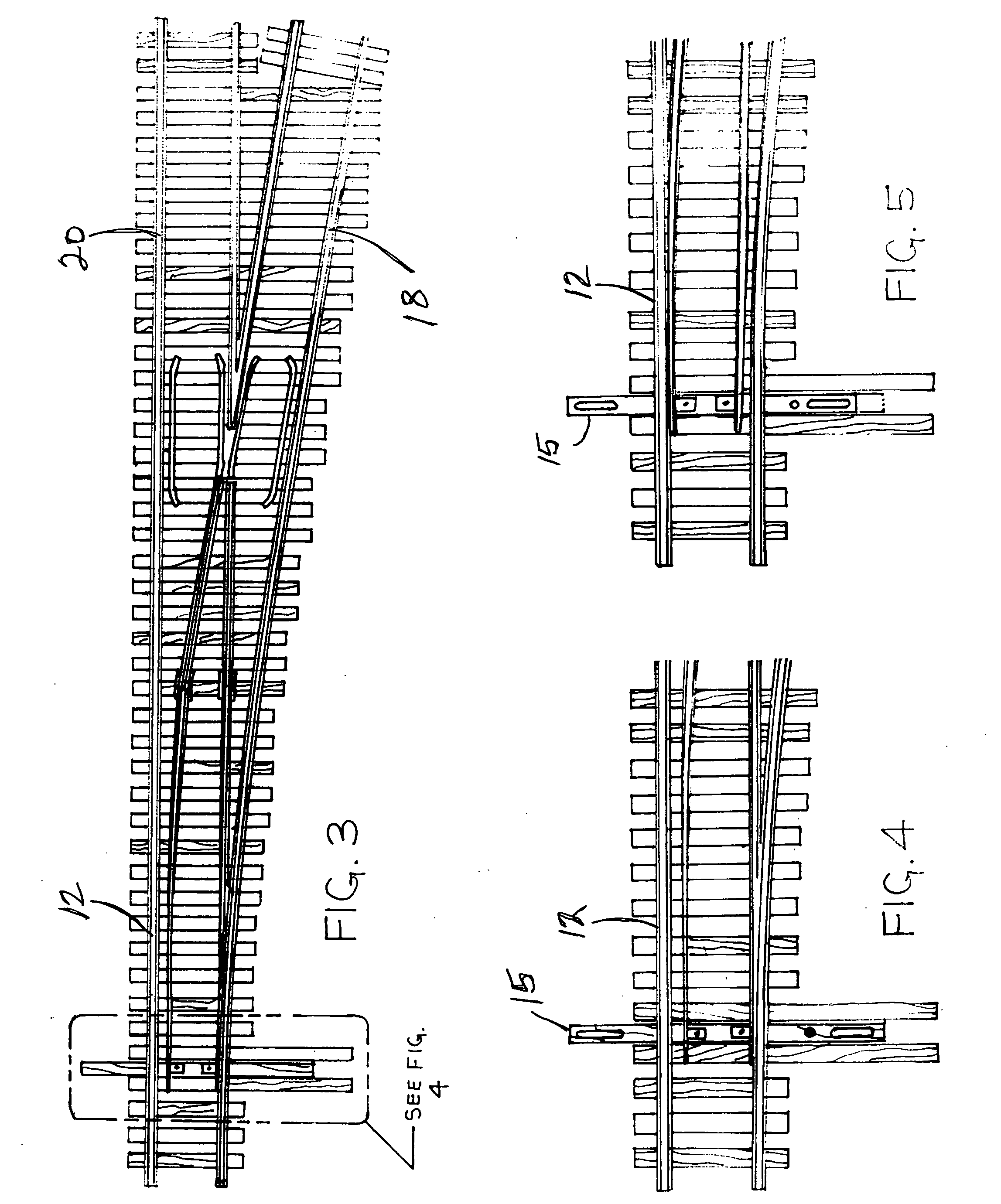
[0026]Referring to the accompanying figures, it will be seen that a track switch actuator assembly 10 is mounted directly to the bottom of a track switch 12 in a model train layout 21 on which there is at least one model train 14. The actuator assembly 10 is preferably hidden in or partially obscured by a simulated track bed 16 as shown best in FIGS. 1 and 2. As seen best in FIGS. 3 to 7, the actuator assembly 10 is secured to the track switch 12 which is, in turn, connected to a turn out track piece 18 and a straight track piece 20. Of course, it will be understood that this turn out track configuration is shown by way of example only and that the present invention may be implemented in various other track switching configurations well known in the art of model railroads. For example, the invention may be used with curved turnouts, wye turnouts, three-way turnouts, double crossovers and the like. It will also be understood that motors used in track switch actuators will either have...


PUM


Abstract

A track switch actuator which has the advantages of slow, smooth realistic operation, small package size that permits hidden installation directly beneath the track switch and unobtrusive, simple design which does not detract from realistic appearance. In fact, the preferred embodiment is sufficiently small to be installed to the bottom of a track switch before the track switch is installed into the layout. In the preferred embodiment of the present invention, a small low voltage DC motor is installed into an elongated ABS plastic extrusion having an elongated radial wall opening. The motor shaft is affixed to a lead screw on which a threaded slider travels from one end to another depending on the direction of lead screw rotation. An actuator arm in the form of a nail-like projection, is soldered or otherwise firmly affixed to the slider exterior so that the projection travels with the slider along the lead screw with the projection extending perpendicularly from the lead screw. The free end of the projection extends into the throw bar of the track switch for switching same with travel along the lead screw.

Description

BACKGROUND OF THE INVENTION[0001]1. Field of the Invention[0002]The present invention relates generally to model railroad switches and more particularly to a model railroad switch assembly, which employs a lead screw actuator driven by an electric motor.[0003]2. Background Art[0004]Historically, the actuators for implementing a track switch for redirecting miniature rolling stock comprise solenoid coils. Such coils are typically configured for moving a plunger, which is connected to the track switch through a linkage. Unfortunately, such solenoid coil based switches are not very good simulations because they move quickly in a pulse-like motion and not in a slow steady motion which would be much more realistic in its operation. In an effort to provide a more realistic deliberate and steady switching motion, prior art switch machines have been substituting an electric motor operated switch for a solenoid coil operated switch. One example of such a prior art electric motor type actuato...

Claims


Application Information

Patent Timeline
IPC IPC(8): A63H19/32
CPCA63H19/32
Inventor HEMPHILL, LEWIS
Owner HEMPHILL LEWIS
Why Eureka
Try Eureka