Flashlight with multistage switch and ARC lamp operation sensor

a multi-stage switch and operation sensor technology, applied in the direction of sustainable buildings, incandescent lamp energy saving, lighting and heating apparatus, etc., can solve the problems of excessive battery consumption, insufficient illumination, and limited light levels of tungsten filament lamps

Active Publication Date: 2008-07-31
SUREFIRE LLC
View PDF5 Cites 22 Cited by
  • Summary
  • Abstract
  • Description
  • Claims
  • Application Information

AI Technical Summary

Benefits of technology

[0008]The present invention overcomes the limitations of the prior art by providing a flashlight having a body containing control circuitry, with a lamp connected to the body and to the control circuitry. A photodetector is connected to the body and the control circuitry, and faces the lamp to sense an operating condition of the lamp. The control circuitry operates the lamp in a start up mode until signaled by the photodetector that the lamp is properly operating. After this, the lamp is operated in a normal mode. The flashlight may have a switch with a button that moves through a range of positions. The switch may have several contact elements, and the button may have an actuator registered with each of the contact elements. The actuators may be of different heights, to provide a sequence of switch operation. Some of the actuators may be movable to allow the button to be actuated further after an initial contact is made.

Problems solved by technology

The principal light source used in flashlights is the tungsten filament lamp, as alternatives suffer inadequate illumination, or excessive battery consumption.
Tungsten filament lamps, however, are limited in their ability to generate extremely high light levels.
However, HID lamps do not start up simply by applying the operating voltage.
If the start up mode were continued indefinitely, energy would be wasted, operation compromised, and damaged risked.
However, this may overstress the lamp or be inadequate duration, depending on conditions.
For some applications, the contacts may be fouled by arcing when the contacts are in close proximity, but not firmly in contact.

Method used


Image

  • Flashlight with multistage switch and ARC lamp operation sensor
  • Flashlight with multistage switch and ARC lamp operation sensor
  • Flashlight with multistage switch and ARC lamp operation sensor

Examples


Embodiment Construction

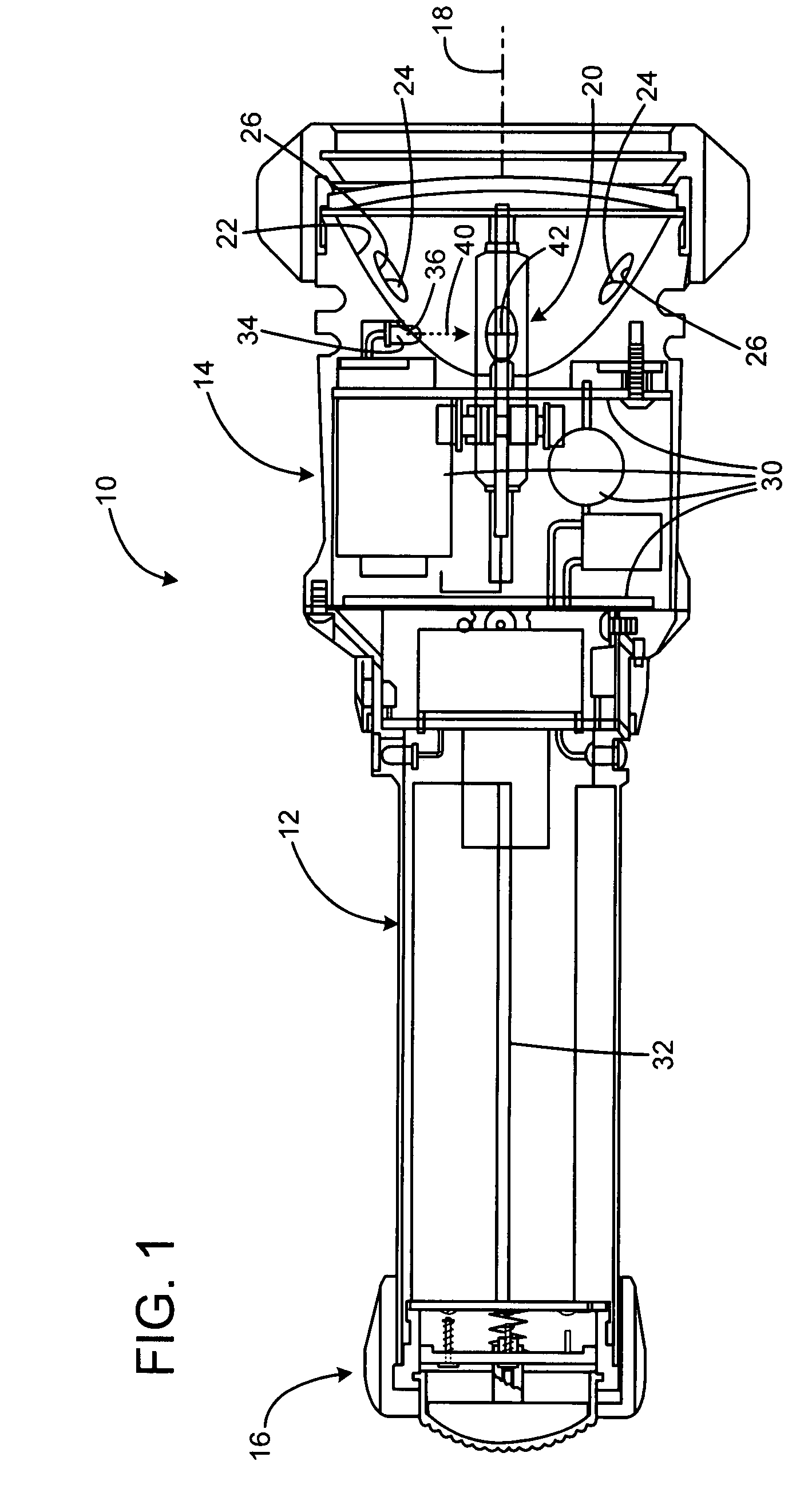
[0014]FIG. 1a shows a flashlight 10 according to a preferred embodiment of the invention. The flashlight includes a major housing portion 12 having a head 14 connected at a forward end, and a rear tailcap 16 connected at a rear end, and having a switch 17 that will be discussed in detail below. The major portions of the housing are cylindrical, and define an axis 18. The head 14 includes an arc lamp 20 at the focus of a reflector 22 that projects a beam in the forward direction when the light is operated. Peripheral LED lamps 24 are projected forward, and reside in apertures 26 in the reflector.

[0015]Power and control circuitry 30 is connected to the lamp 20 and lamps 26, and to batteries 32 in the housing 12. A photodetector 34 is also connected to the circuitry, and is positioned within an aperture 36 in the reflector 22. The photodetector defines an optical axis 40 that is perpendicular to the optical axis 18, and which intersects a central illumination point 42 of the arc lamp 2...


PUM


Abstract

A flashlight has a body containing control circuitry, with a lamp connected to the body and to the control circuitry. A photodetector is connected to the body and the control circuitry, and faces the lamp to sense an operating condition of the lamp. The control circuitry operates the lamp in a start up mode until signaled by the photodetector that the lamp is properly operating. After this, the lamp is operated in a normal mode. The flashlight may have a switch with a button that moves through a range of positions. The switch may have several contact elements, and the button may have an actuator registered with each of the contact elements. The actuators may be of different heights, to provide a sequence of switch operation. Some of the actuators may be movable to allow the button to be actuated further after an initial contact is made.

Description

FIELD OF THE INVENTION[0001]This invention relates to HID (high-intensity discharge) flashlights and switching mechanisms, and more particularly to switching for multiple states.BACKGROUND OF THE INVENTION[0002]Flashlights are conveniently-sized battery powered portable light sources, which provide the user with a source of illumination. The illumination could be white light or light of a specific color, or even light outside the visible range of wavelengths, such as ultra violet or infrared radiation. The “color” or wave length of the light will depend on the nature of the light source or light sources used in the flashlight. These would typically be either tungsten lamps, ARC lamps, light emitting diodes (LEDs), lasers, or any other emitter.[0003]Because of the general nature of flashlights and their wide range of applications, it is very desirable for a flashlight to be able to emit, at the user's direction, different levels of light output, different colors or wavelengths of lig...

Claims


Application Information

Patent Timeline
Patent Type & Authority Applications(United States)
IPC IPC(8): H05B39/00H01H19/46
CPCF21V23/0421Y02B20/14H05B39/041H01H13/64Y02B20/00
Inventor KIM, PAUL Y.HUNT, WILLIAM A.TANG, LAI CHANG
Owner SUREFIRE LLC
Why Eureka
Try Eureka