Cell balancing battery pack and method of balancing the cells of a battery

a cell and battery pack technology, applied in the field of circuitry and a method of balancing the discharge of battery cells, can solve the problems of battery cells leaking energy, battery cells not having an infinite life span, and affecting the service/maintenance of secondary cells,

Inactive Publication Date: 2008-07-31
GENERAL ELECTRIC CO
View PDF18 Cites 75 Cited by
  • Summary
  • Abstract
  • Description
  • Claims
  • Application Information

AI Technical Summary

Benefits of technology

[0008]An embodiment of the battery in the present disclosure comprises a plurality of cells that produce a battery charge and the battery comprises a plurality of switches connect...

Problems solved by technology

While the rechargeable battery cells provide a convenient source of power, the rechargeable battery cells do not have an infinite life span and the ability of the cells to hold a charge degrades over the lifetime of the cell.
Furthermore, battery cells leak energy and lose charge during periods of non-use or storage.
These periods of non-use may occur while the cells are being held by a manufacturer before the cells are assembled into a battery, or while the cells are assembled into the battery, but the battery has not yet been sold, or during long periods of non-use of the battery by the consumer.
The cell leakage is exacerbated by the presence of heat, which may affect batteries that are not stored in a temperature controlled environment.
Alternatively, the cell leakage due to heat may affect a battery, such as a back up battery, that is held in close proximity to other normally operating electrical circuits that give off heat.
Furthermore, due to the internal resistance of the battery, battery cells may not discharge evenly within the battery.
These different levels of charge can result in unpredictable indications of low battery and possible inadvertent power shut downs.
Therefor...

Method used


Image

  • Cell balancing battery pack and method of balancing the cells of a battery
  • Cell balancing battery pack and method of balancing the cells of a battery
  • Cell balancing battery pack and method of balancing the cells of a battery

Examples


Embodiment Construction

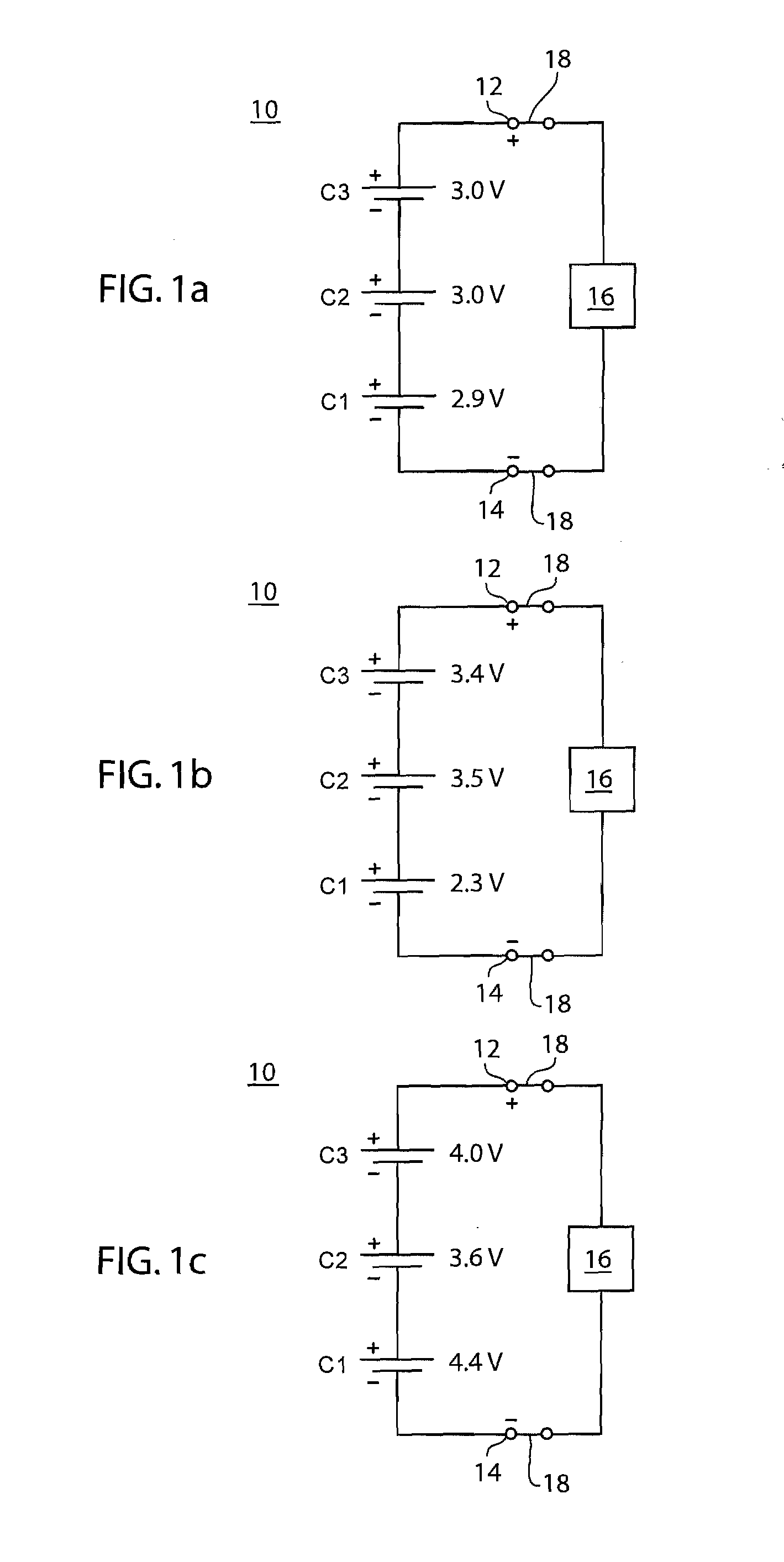
[0020]FIGS. 1a-c depict a series of schematic diagrams of a battery 10 comprising electrical cells C1, C2, and C3 connected in series. The battery 10 comprises a positive terminal 12 and a negative terminal 14. The total charge of the battery 10 is the voltage between the positive terminal 12 and the negative terminal 14. An electronic device 16 or other type of electrical load is connected to the battery 10 at the positive terminal 12 and the negative terminal 14 by a load switch 18. The load switch 18 may alternatively be another form of suitable electrical connection between the electronic device 16 and the terminals 12 and 14, respectively, that is not necessarily a switch. When the battery 10 is connected to the electronic device 16, the battery 10 provides the electronic device 16 with a supply of electrical charge. The electronic device 16 uses this charge to operate.

[0021]Cells C1, C2, and C3 are connected in series; therefore the individual voltage of each of the cells is s...


PUM


Abstract

A battery with a battery balancing assembly that regulates the discharge of battery cell charge and a method of evenly discharging battery cells, the battery comprising a plurality of cells. The balancing assembly includes switches disposed between the cells such that the switches may configure the cells in a normal configuration and a balance configuration, wherein in the normal configuration the plurality of cells may be connected to an electronic device and wherein in the balance configuration the plurality of cells are connected to a balancing circuit. The balancing circuit serving to balance the charge in the plurality of cells prior to the recharging of the cell.

Description

FIELD OF THE DISCLOSURE[0001]The present disclosure relates to the field of rechargeable batteries and energy cells for rechargeable batteries. More specifically, the present disclosure relates to circuitry and a method for balancing the discharge of battery cells.BACKGROUND OF THE DISCLOSURE[0002]Batteries are a convenient source of electrical energy for many types of portable and / or mobile electronics. A typical battery is formed by the connection of a number of electrical cells connected in a series configuration. Many types of batteries include rechargeable cells, such that when an outside energy source is applied to the battery cells energy is stored within the cells. While many chemical combinations for the cathode and the anode of the battery cells exist, some commonly used combinations include nickel cadmium (NiCd), nickel metal hydride (NiMH), and lithium ion (Li-Ion) compositions.[0003]While the rechargeable battery cells provide a convenient source of power, the rechargea...

Claims


Application Information

Patent Timeline
IPC IPC(8): H02J7/00H01M10/44
CPCH01M10/052H02J7/0024H02J7/0016H01M10/441Y02E60/10
Inventor KOSKI, ROY DONALDLINDQUIST, PAUL DANIEL
Owner GENERAL ELECTRIC CO
Why Eureka
Try Eureka