
Eas Reader Detecting Eas Function From Rfid Device

a technology of rfid and reader, applied in the field of integrated electronic article surveillance and radiofrequency identification system, can solve the problems of previously known combination of eas and rfid devices or tags or labels, cost, and degradation of performance, and achieve the effect of reducing the cost of a retailer or manufacturer, and reducing the cost of a combination of eas and rfid tags or labels

Inactive Publication Date: 2008-07-31
TYCO FIRE & SECURITY GMBH
View PDF12 Cites 19 Cited by
  • Summary
  • Abstract
  • Description
  • Claims
  • Application Information

AI Technical Summary

Benefits of technology

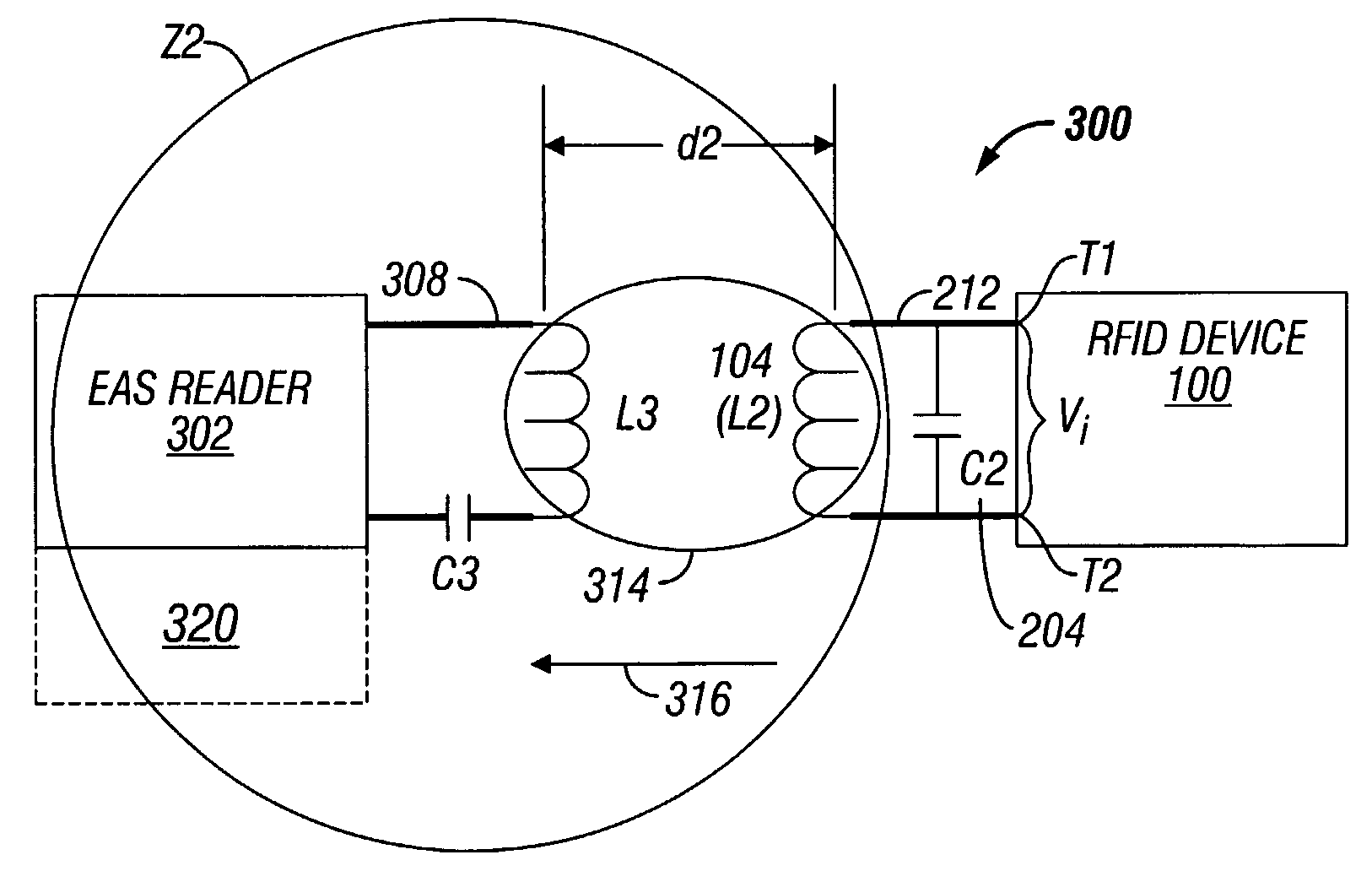
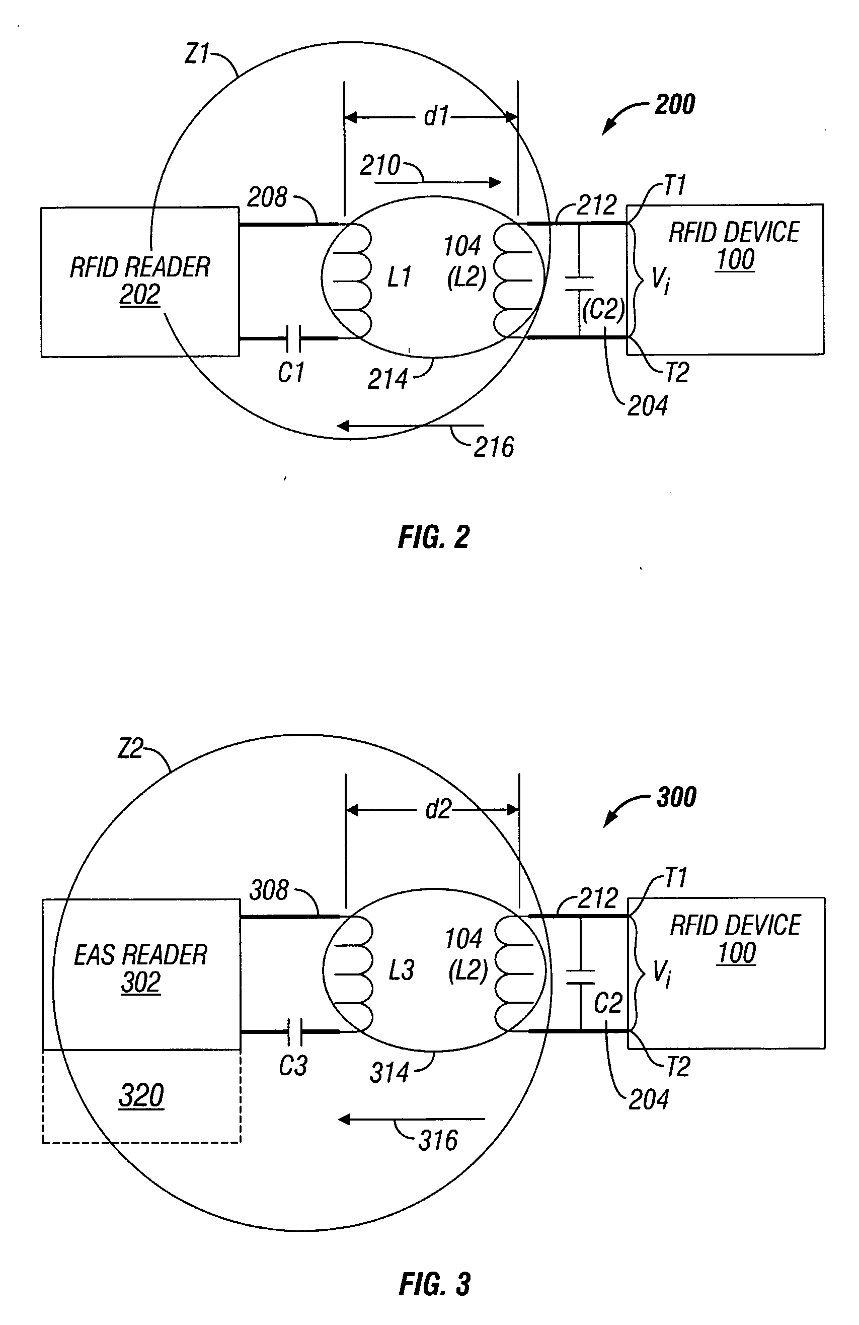
[0011]It is an object of the present disclosure to perform an EAS function with an EAS reader coupled to an RFID label or device. It is also an object of the present disclosure to provide an integrated EAS and RFID system which can detect the presence of an RFID device with a resonant circuit based on or due to resonance of the circuit.
[0012]It is another object of the present disclosure to provide an EAS reader integrated into an RFID system so as to permit a larger detection distance or read range than that available from a conventional EAS reader and EAS label combination. The present disclosure relates also to an EAS detection system configured to have a smaller, lower cost label with greater simplicity.

Problems solved by technology

However, there are several issues pertaining to previously known combination EAS and RFID devices or tags or labels.
Cost—combined EAS / RFID tags or labels are generally more expensive for a retailer or manufacturer since two devices and two separate readers or deactivators are typically required.
Size—the size of a combined configuration is generally larger and typically any amount of physical overlapping results in degradation of performance.
Interference—interference can occur, if the devices are overlapped resulting in degrading performance of either or both EAS and RFID functions, unless specific design features are provided to reduce the interference caused by the overlapping.

Method used


Image

  • Eas Reader Detecting Eas Function From Rfid Device
  • Eas Reader Detecting Eas Function From Rfid Device
  • Eas Reader Detecting Eas Function From Rfid Device

Examples


Embodiment Construction

[0029]Numerous specific details may be set forth herein to provide a thorough understanding of the embodiments of the invention. It will be understood by those skilled in the art, however, that various embodiments of the invention may be practiced without these specific details. In other instances, well-known methods, procedures, components and circuits have not been described in detail so as not to obscure the various embodiments of the invention. It can be appreciated that the specific structural and functional details disclosed herein are representative and do not necessarily limit the scope of the invention.

[0030]It is worthy to note that any reference in the specification to “one embodiment” or “an embodiment” according to the present disclosure means that a particular feature, structure, or characteristic described in connection with the embodiment is included in at least one embodiment. The appearances of the phrase “in one embodiment” in various places in the specification a...


PUM


Abstract

A reader device for electronic article surveillance (EAS) is disclosed which includes an exciter; a transmitter, the transmitter operatively coupled to the exciter via a first signal gate; a transmitter antenna operatively coupled to the transmitter; a receiver antenna operatively coupled to a receiver front end; and a signal detector, the receiver front end operatively coupled to the signal detector via a second signal gate, wherein the exciter generates a burst of electromagnetic energy in a pulse or a continuous wave at an operating frequency of a radiofrequency identification (RFID) tag within a read range of the EAS reader such that the energy level of the burst generates a residual or ring-down signal from the RFID tag indicating the presence of the RFID tag without activating the RED functions of the tag. The ring-down signal is read by the EAS reader as an EAS function.

Description

CROSS-REFERENCE TO RELATED APPLICATIONS[0001]This application claims the benefit of priority under 35 U.S.C. §119 of U.S. Provisional Patent Application Ser. No. 60 / 629,571 filed on Nov. 18, 2004 entitled “INTEGRATED 13.56 MHz EAS / RFID DEVICE”, the entire contents of which are incorporated by reference herein.BACKGROUND OF THE INVENTION[0002]1. Technical Field[0003]This invention relates to an integrated electronic article surveillance (EAS) and radiofrequency identification (RFID) system which is capable of performing dual EAS / RFID functions at the RFID designated frequency of 13.56 MHz and particularly to a device which is capable of detecting an EAS detection signal from an RFID device at the RFID designated frequency of 13.56 MHz without activating the RFID functions of the RFID device.[0004]2. Background of Related Art[0005]With the advent of RFID technology, many retailers are considering tagging merchandise (e.g., per item, per case, per pallet) with RFID tags. At the same ti...

Claims


Application Information

Patent Timeline
IPC IPC(8): G08B13/14
CPCG06K7/10128G08B13/2417G08B13/2414G08B13/24G08B13/22G06K17/00G08B13/00
Inventor LIAN, MING-RENSHAFER, GARY MARK
Owner TYCO FIRE & SECURITY GMBH
Learn More