Simulation system implementing real-time machine data

a simulation system and machine data technology, applied in the field of simulation systems, can solve the problems of limited and costly use of onboard operators, ineffective, time-consuming and labor-intensive, etc., and achieve the effects of reducing the risk of accidents, reducing the efficiency of the system, and increasing the cost of operation

Active Publication Date: 2008-07-31
CATERPILLAR INC
View PDF18 Cites 130 Cited by
  • Summary
  • Abstract
  • Description
  • Claims
  • Application Information

AI Technical Summary

Benefits of technology

[0008]In accordance with one aspect, the present disclosure is directed toward a machine simulation and control system. The machine simulation and control system may include a user interface configured to display a simulated environment. The machine simulation and control system may also include a controller in communication with the user interface and a remotely located machine. The controller may be configured to receive from the machine real-time information related to operation of the machine at a worksite. The controller may also be configured to simulate the worksite, operation of the machine, and movement of a machine tool based on the received information. The controller may further be configured to provide to the user interface the simulated worksite, operation, and movement in the simulated environment.
[0009]According to another aspect, the present disclosure is directed toward a method of remotely controlling a machine. The method may include monitoring machine operation and simulating in real-time a worksite, machine movement within the worksite, and machine tool movement within the worksite based on the monitored machine operation. The method may further include receiving machine control instructions at a location remote from the machine, and affecting operation of the machine in response to the received instructions.

Problems solved by technology

During the performance of these tasks, the machines may operate in situations that are hazardous to an operator, under extreme environmental conditions uncomfortable for the operator, or at work locations remote from civilization.
Because of these factors, the completion of some tasks by an onboard operator can be dangerous, expensive, labor intensive, time consuming, and inefficient.
Although this strategy of remotely controlling the machines may have been successful in some situations, its use was limited and costly.
Specifically, the visual representation of the machine and environment was typically limited to the number of cameras mounted to the machine and the view angles provided by those cameras.
Because the number of cameras on the machine relates directly to cost and, because the harsh environment of the worksite reduced the component life of the cameras, the initial and operating costs of the system were significant.
In addition, wireless video feed in real-time requires large bandwidth, thereby further increasing the operating cost of the system.
Although the system of the '078 patent may provide a lower cost, more robust way to remotely view and control motions of construction equipment, its use may still be limited.
In particular, because the system of the '078 patent provides a visual representation of only the boom, stick, and bucket, the operator may be unable to properly control engagement of the backhoe with its surrounding environment.
In particular, without a representation of the worksite or an excavation surface at the work site, it may be very difficult, if not impossible, to adequately engage the bucket with the excavation surface.
In addition, with the minimal visual representation described above, the operator may be unable to remotely move or orient the backhoe itself, or perform other necessary machine tasks.

Method used


Image

  • Simulation system implementing real-time machine data
  • Simulation system implementing real-time machine data
  • Simulation system implementing real-time machine data

Examples


Embodiment Construction

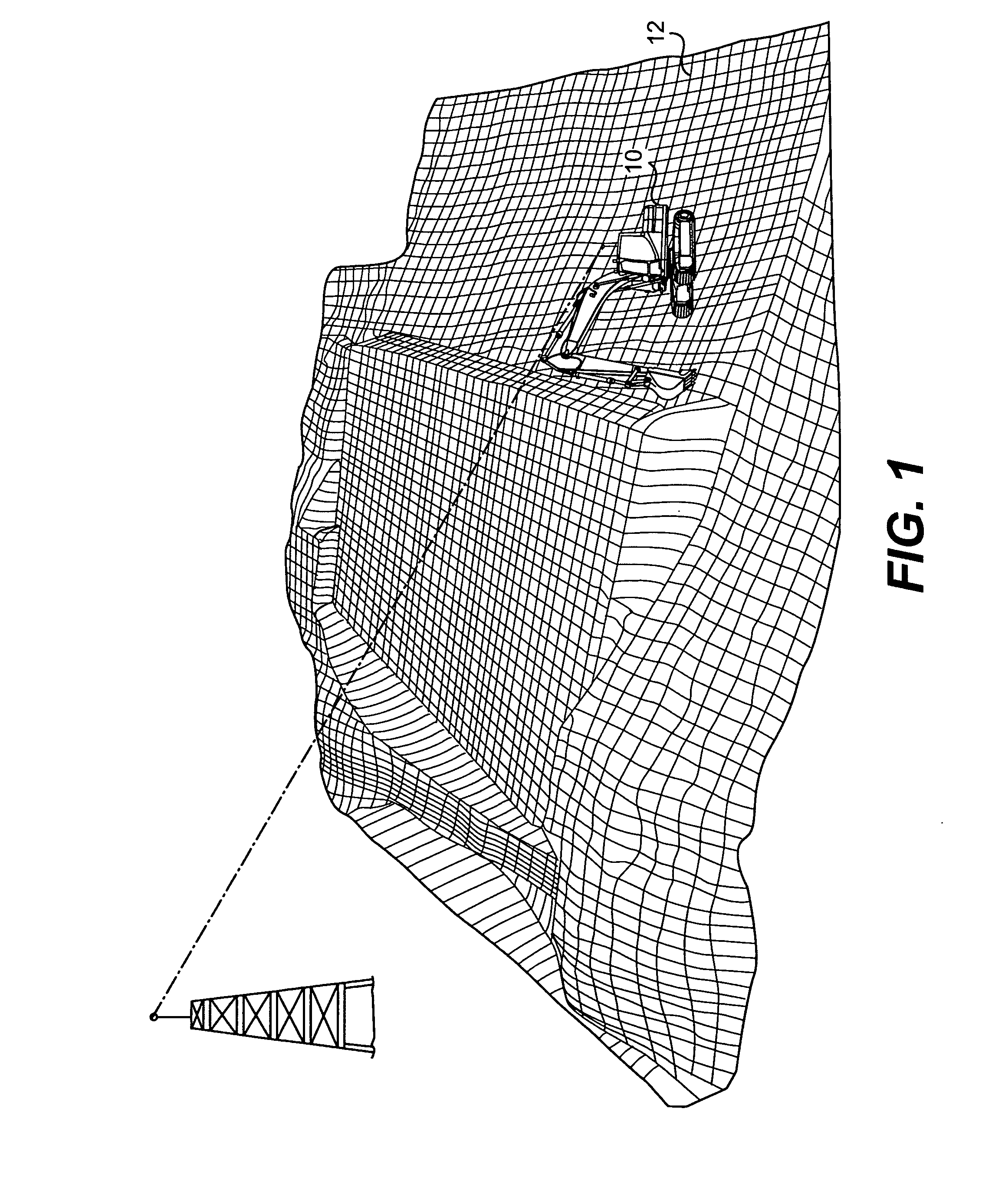
[0014]FIG. 1 illustrates an exemplary machine 10 performing a predetermined function at a worksite 12. Machine 10 may embody a stationary or mobile machine, with the predetermined function being associated with a particular industry such as mining, construction, farming, transportation, power generation, or any other industry known in the art. For example, machine 10 may be an earth moving machine such as the excavator depicted in FIG. 1, in which the predetermined function includes the removal of earthen material from worksite 12 that alters the geography of worksite 12 to an architecturally desired form. Machine 10 may alternatively embody a different earth moving machine such as a motor grader or a wheel loader, or a non-earth moving machine such as a passenger vehicle, a stationary generator set, or a pumping mechanism. Machine 10 may embody any suitable operation-performing machine.

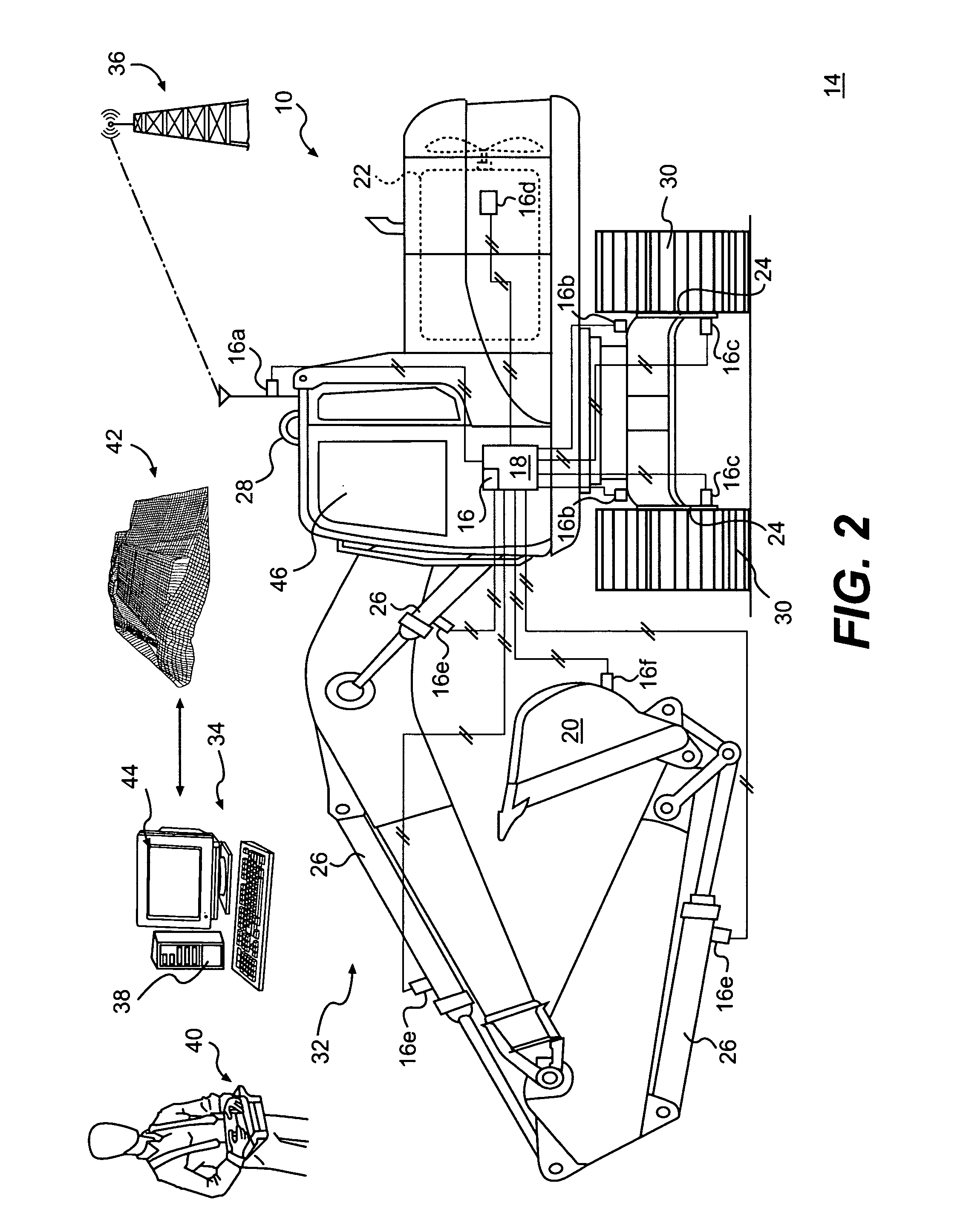
[0015]As illustrated in FIG. 2, machine 10 may include a simulation system 14 having multiple com...


PUM


Abstract

A simulation and control system for a machine is disclosed. The simulation and control system may have a user interface configured to display a simulated environment. The machine simulation and control system may also have a controller in communication with the user interface and a remotely located machine. The controller may be configured to receive from the machine real-time information related to operation of the machine at a worksite. The controller may also be configured to simulate the worksite, operation of the machine, and movement of a machine tool based on the received information. The controller may further be configured to provide to the user interface the simulated worksite, operation, and movement in the simulated environment.

Description

TECHNICAL FIELD[0001]This disclosure relates generally to a simulation system and, more particularly, to a system that uses real-time performance data to remotely simulate operation of a machine at a worksite.BACKGROUND[0002]Machines such as, for example, excavators, loaders, dozers, motor graders, haul trucks, and other types of heavy equipment are used to perform a variety of tasks. During the performance of these tasks, the machines may operate in situations that are hazardous to an operator, under extreme environmental conditions uncomfortable for the operator, or at work locations remote from civilization. Because of these factors, the completion of some tasks by an onboard operator can be dangerous, expensive, labor intensive, time consuming, and inefficient.[0003]One solution to this problem may include remotely controlling the machines. Specifically, an offboard operator located remotely from the machine, if provided with a visual representation of the machine and the work e...

Claims


Application Information

Patent Timeline
Patent Type & Authority Applications(United States)
IPC IPC(8): H04N7/00
CPCG05D1/0044G09B9/048G05D2201/0202
Inventor STRATTON, KENNETH L.SHULTS, JAMIECLAR, JEAN-JACQUESDARBY, DERRICKOPDENBOSCH, AUGUSTO J.SANTAMARIA, JUAN CARLOS
Owner CATERPILLAR INC
Why Eureka
Try Eureka