3-D Imaging System

Active Publication Date: 2008-07-31
IEE INT ELECTRONICS & ENG SA
View PDF6 Cites 42 Cited by
  • Summary
  • Abstract
  • Description
  • Claims
  • Application Information

AI Technical Summary

Benefits of technology

[0010]In order to further improve synchronization, the means for generating an electrical reference signal is preferably placed contiguous to at least one light source of the illumination unit. By minimizing optical and/or electrical signal line lengths, the phase of the reference signal has maximum correspondence with the phase of the emitted light. As will be appreciated, the means for generating an electrical reference signal is operatively independent of the imaging sensor. Accordingly, no mechanical modifications on the imaging sensor are required when improving synchronization according to the present invention.
[0011]In a first embodiment, the means for generating an electrical reference signal comprises a shunt resist

Problems solved by technology

Due to the high propagation speed given by the velocity of light, a fundamental difficulty encountered in distance measurements based on the TOF or phase-shift method resides in the required temporal resolution of the measurement device.
Actual problems in this respect are unknown variations and drift

Method used


Image

  • 3-D Imaging System
  • 3-D Imaging System
  • 3-D Imaging System

Examples


Example

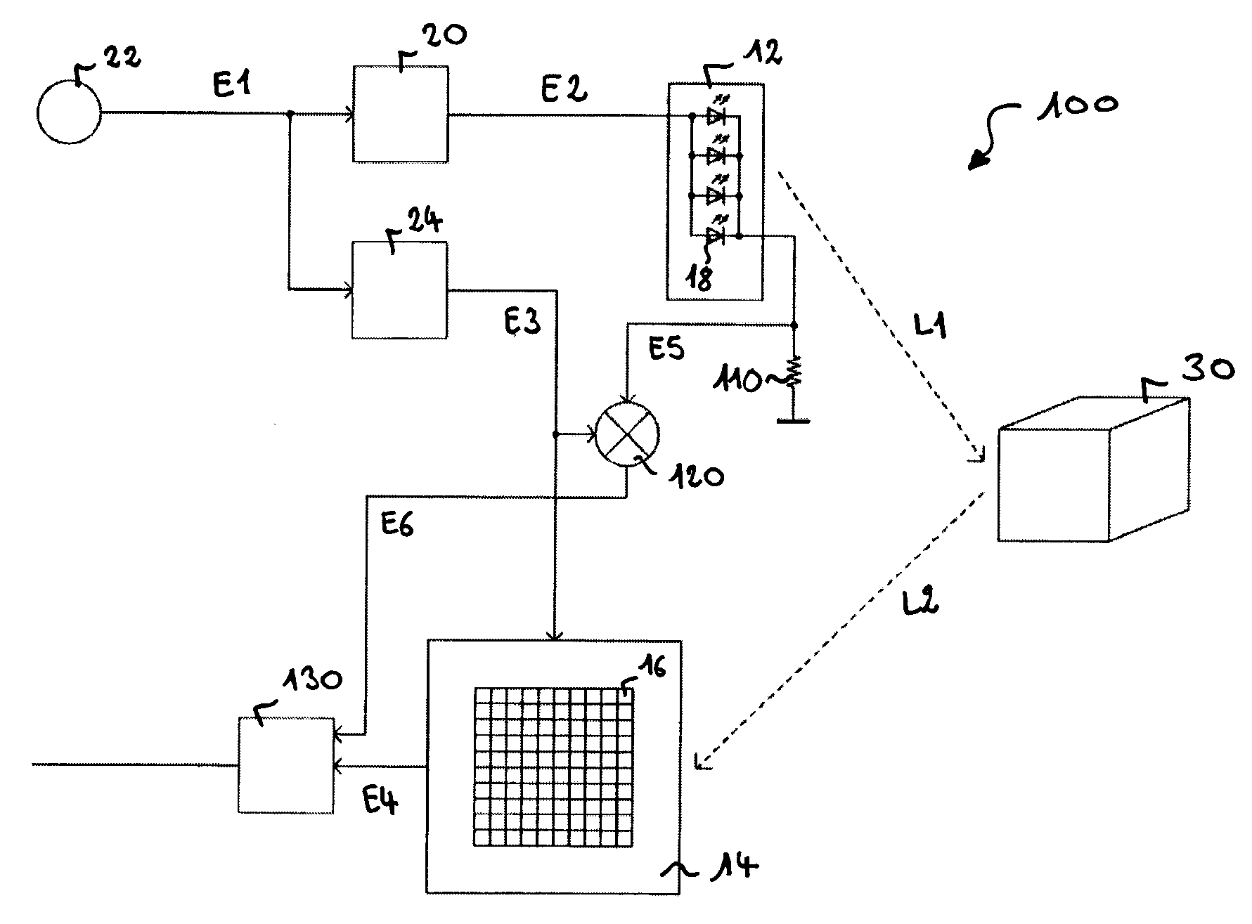
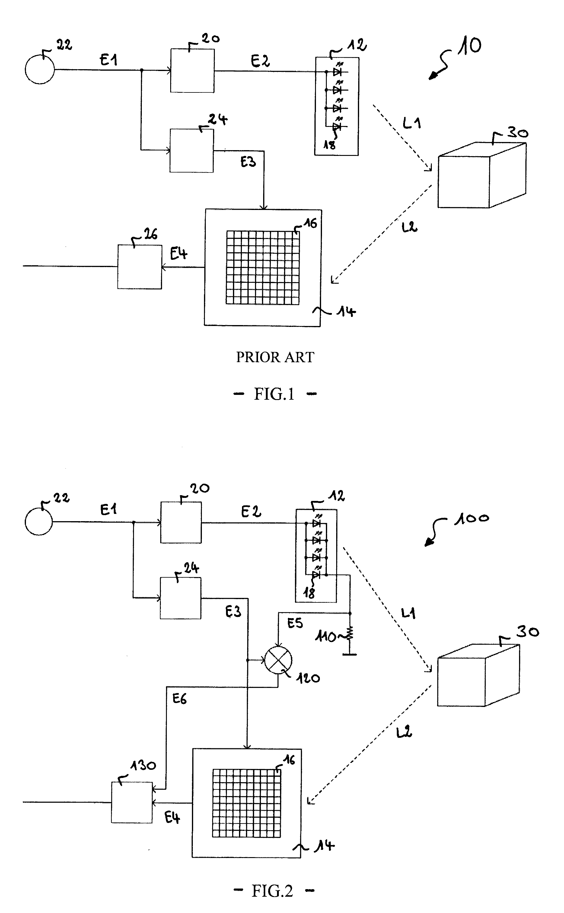
[0025]FIG. 2 shows a 3-D imaging system 100 according to a first embodiment. A shunt resistor 110 is connected in series to the light emitting devices 18 of the illumination unit 12 and to a ground terminal. The shunt resistor 110 provides a voltage proportional to the illumination current through the light emitting devices 18. This voltage is fed as an electrical reference signal E5 to a mixer element 120. In order to maximize the correspondence between the electrical reference signal E5 and the absolute temporal behaviour of the light signal L1 (at the illumination unit 14), the resistor 110 is placed as close as possible to the light emitting devices 18, within the illumination unit 12. Inevitable propagation times can however be taken into account during final evaluation in an evaluation unit 130. The mixer element 120 has essentially the same properties, in particular essentially the same transfer function, as the individual sensor cells 16 of the imaging sensor 14 with the exc...

Example

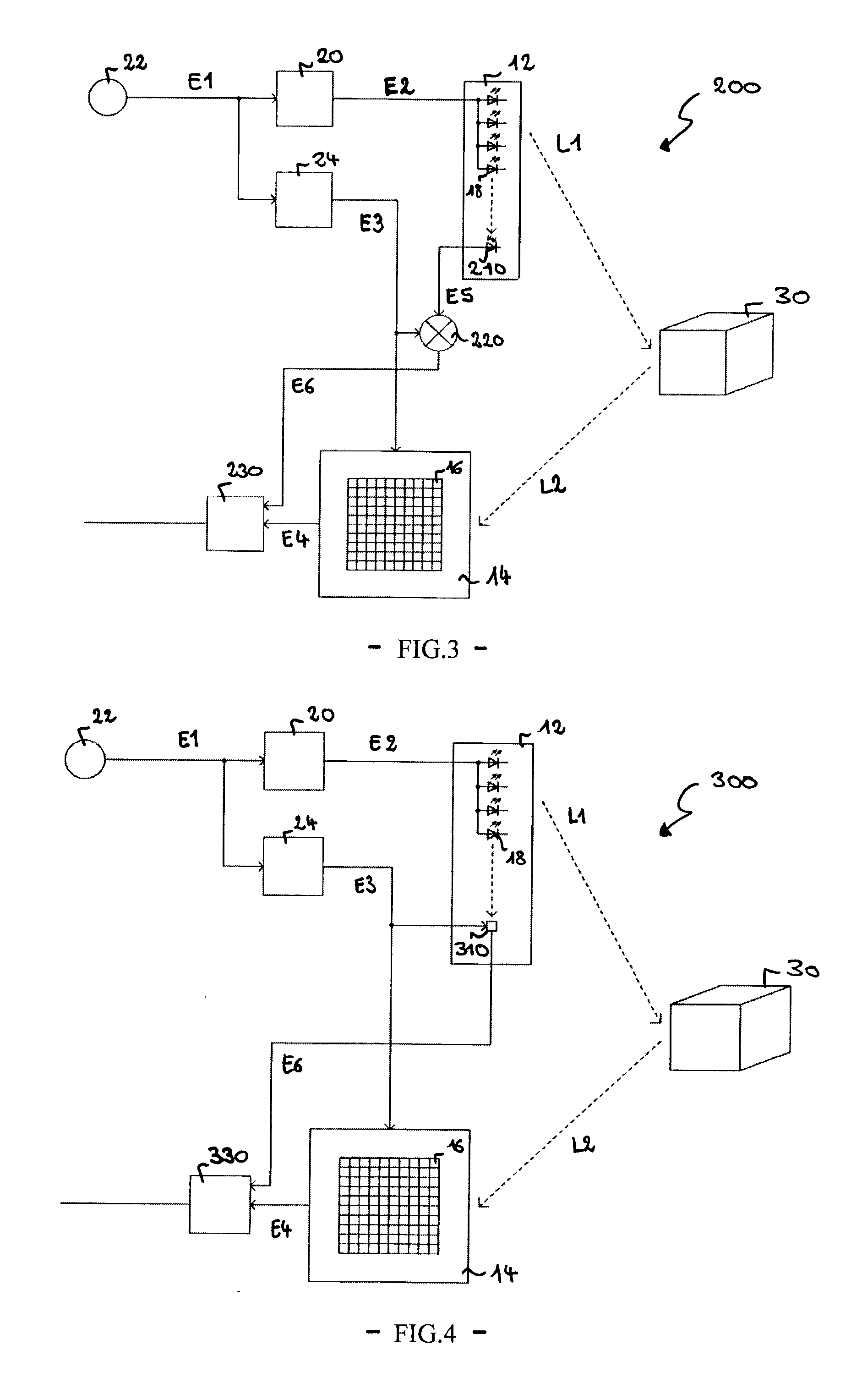
[0026]A second embodiment is shown in FIG. 3. The 3-D imaging system 200 of FIG. 3 essentially corresponds to the system of FIG. 2. The major difference in the 3-D imaging system 200 resides in a different means for generating the electrical reference signal E5. As seen in FIG. 3, a photodiode 210 is mounted in the illumination unit 12 contiguous to the light emitting devices 18. The photodiode 210 directly derives the electric reference signal E5 from the emitted light signal L1 by photoelectric conversion. A mixer element 220 receives the output current of the photodiode 210 and the demodulation signal E3 at its input and provides a synchronization signal E6 at its output. Similar to the mixer element 120 of FIG. 2, the mixer element 220 is designed to imitate, together with the photodiode 210, the function of a sensor cell 16 of the imaging sensor 14. Other characteristics of the 3-D imaging system 200 are identical to those of the 3-D imaging system 100 described with respect to...


PUM


Abstract

A 3-D imaging system is described. The 3-D imaging system comprises an illumination unit for emitting light onto a target scene, an imaging sensor for imaging the target scene by detecting scattered/reflected light, an evaluation unit for determining distance information related to the target scene on the basis of light propagation time and synchronization means for providing synchronization information to the evaluation unit. The synchronization means comprises means for generating an electrical reference signal in the illumination unit, the reference signal being directly derived from the emitted light.

Description

TECHNICAL FIELD OF THE INVENTION[0001]The present invention relates to a 3-D (three-dimensional) imaging system.BRIEF DESCRIPTION OF RELATED ART[0002]Systems for creating a 3-D representation of a given portion of space have a variety of potential applications in many different fields. Examples are automotive sensor technology (e.g. vehicle occupant detection and classification), robotic sensor technology (e.g. object identification) or safety engineering (e.g. plant monitoring) to name only a few. As opposed to conventional 2-D imaging, a 3-D imaging system requires depth information about the target scene, i.e. the distances between one or more observed objects and an optical receiver of the system need to be determined. A well known approach for distance measurement, which is used e.g. in radar applications, consists in timing the interval between transmission and echo-return of a transmitted measurement signal. This approach is based on the principle that, for a signal with know...

Claims


Application Information

Patent Timeline
IPC IPC(8): G01C3/08
CPCH04N13/0253H04N13/0207H04N13/207H04N13/254
Inventor LAMESCH, LAURENT
Owner IEE INT ELECTRONICS & ENG SA
Why Eureka
Try Eureka