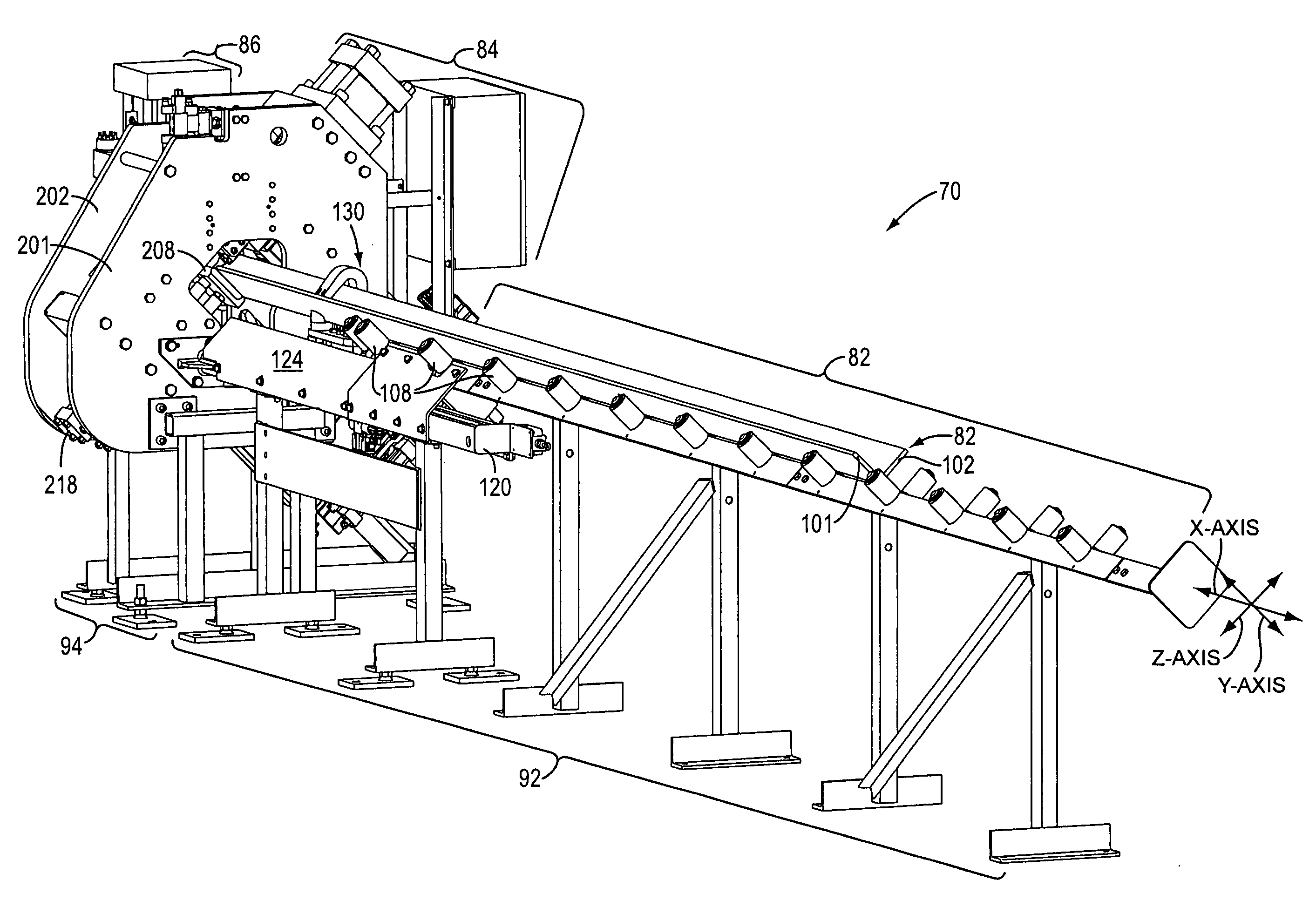
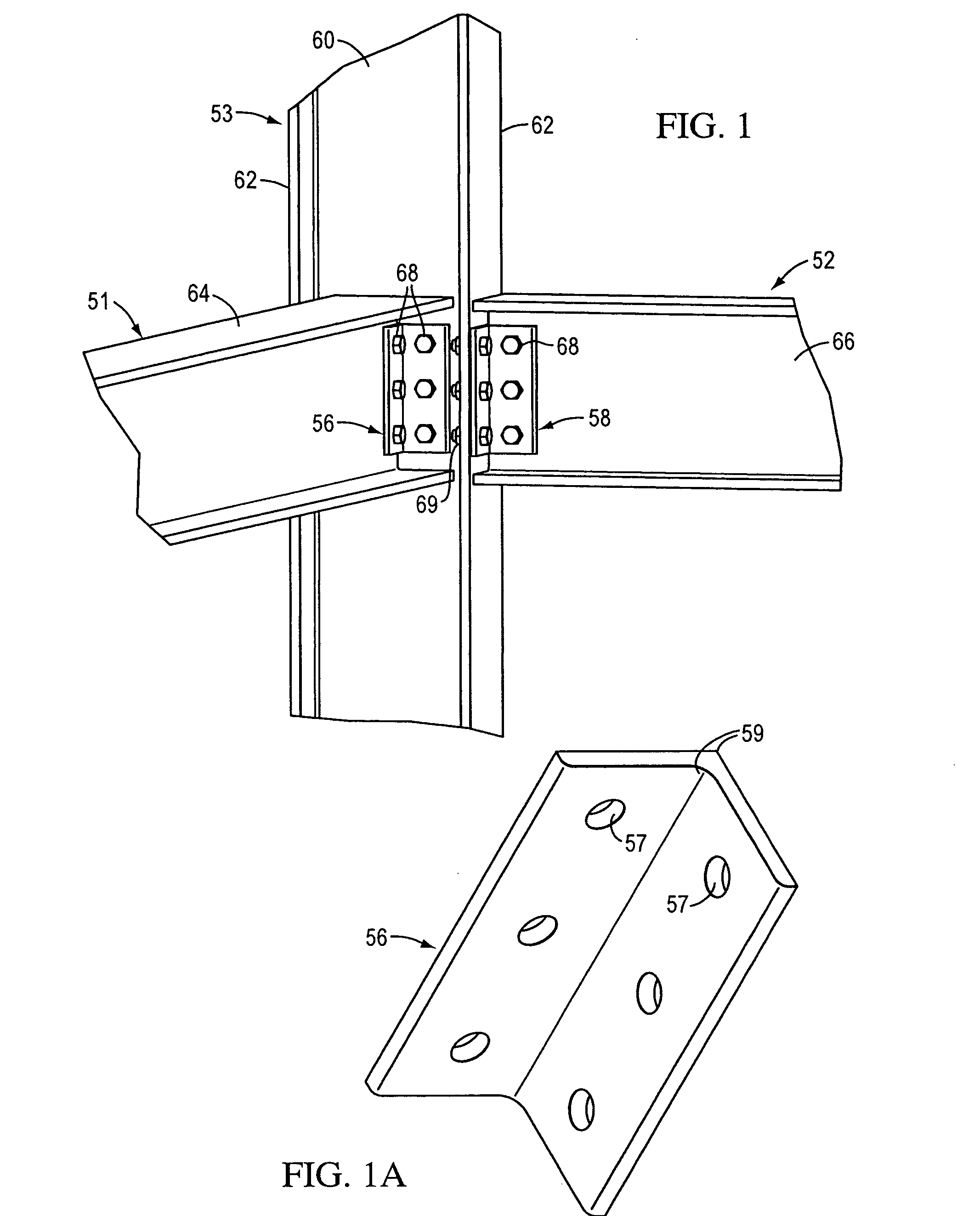
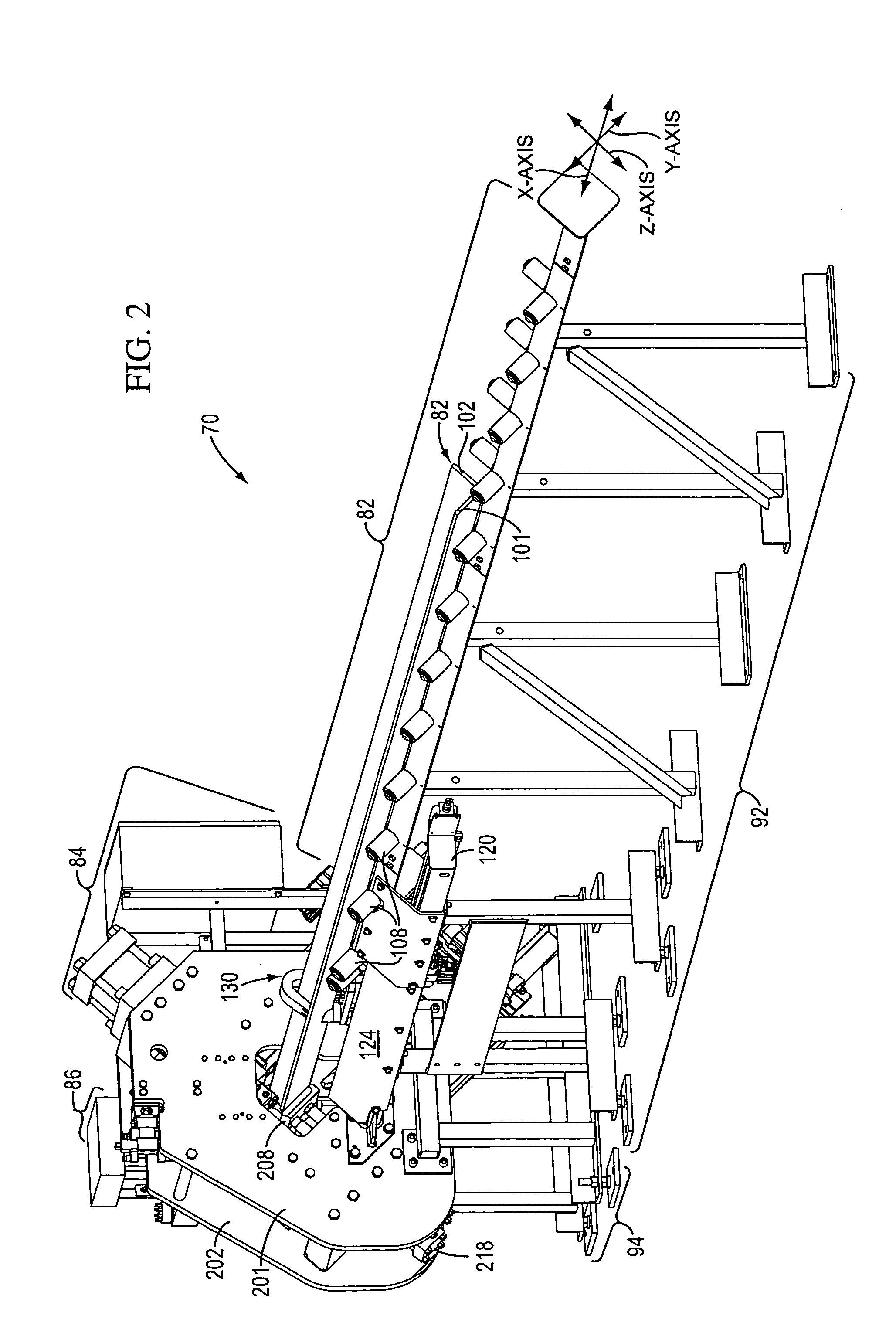
Punch and drill machine for a structural angle

a technology for structural angles and punching machines, applied in the direction of portable punching machines, manufacturing tools, transportation and packaging, etc., can solve the problems of difficult, if not impossible, positioning of punching holes

Inactive Publication Date: 2008-07-31
CARL DAN PEDDINGHAUS
View PDF12 Cites 6 Cited by
  • Summary
  • Abstract
  • Description
  • Claims
  • Application Information

AI Technical Summary

Benefits of technology

[0018]The present invention provides a novel, improved system that can make holes in the legs of a structural angle and that can accommodate designs having some or all of the above-discussed benefits and features.
[0025]In the preferred form of the invention, it is possible to efficiently make a first hole in a first leg of a structural angle, and then make a second hole in the second leg of the structural angle where the first and second holes are “in line” such that the longitudinal axis of the center of the first hole lies in the same plane as the longitudinal axis of the center of the second hole. The two holes can be made without changing the position of the machine components or structural angle relative to the length of the structural angle along the X-axis. Specifically, the first hole can be made with the punch, and then the second hold can be made with the drill without moving the machine components or the structural angle along the X-axis. This makes the process efficient, and this can improve accuracy by eliminating the potential for error associated with additional machine movement.
[0026]Because the first hole in the first leg of the structural angle can be made by the punch, and because the second hole in the second leg of the structural angle can be made by the drill, it is not necessary to provide two separate punches. The use of only one punch instead of two or more punches permits the overall size or length of the machine to be reduced. The reduction results from elimination of a second punch that would otherwise have to be located in side-by-side relationship to the first punch. Further, if a carriage device is used to feed the stock length of angle in the X-axis direction for punching and then through an exit shear, the length of the carriage can be reduced and the length of the carriage movement can be reduced, because the carriage arm does not need to travel into a second punch to position the angle for shearing at a shear located at the exit of such a second punch.
[0027]Because the drill is on the carriage mounted on the second frame which moves the operation axis of the punch along, but perpendicular to, the Y-axis, a preferred form of the invention can employ an accurate positioning feedback system for positioning the punch at the desired Y-axis location along the first leg of the structural angle and also for positioning the distal end of the drill along the Y-axis relative to the second leg of the structural angle. This permits the drill to first be rapidly moved lengthwise along the Y-axis to locate the drill tip near the surface of the second leg of the structural angle, and then be moved slowly at a desired drill feed rate for actually drilling the hole in the angle second leg. The invention also accommodates, where desired, accurate position feedback to control the drill depth.
[0029]The punch has another advantage in that the cost of punch tooling per hole is typically less than the cost of drill tooling per hole. Thus, the capability to produce at least some of the holes with a punch can help reduce or minimize the manufacturing cost. However, in some situations, a punch cannot be used to punch a hole in the leg of a structural angle. For example, if a hole is to be made in the second leg of the angle very close to the opposing first leg of the angle, then a punch cannot punch such a hole because of punch mechanism interference with the opposing leg. In such a case, the present invention permits a hole in the second leg to instead be drilled with the drill. Also, if desired, one or more of the holes in the first leg could be drilled rather than punched, by re-positioning the angle in the machine as might be necessary to locate the first leg against the drill.

Problems solved by technology

Further, because the drill can be used to drill holes in either leg of the angle (by removing and repositioning the angle, if necessary), holes can be drilled in either leg of the angle at locations that would be difficult, if not impossible, to punch.

Method used


Image

  • Punch and drill machine for a structural angle
  • Punch and drill machine for a structural angle
  • Punch and drill machine for a structural angle

Examples


Embodiment Construction

[0073]While this invention is susceptible of embodiment in many different forms, this specification and the accompanying drawings disclose only one specific form as an example of the use of the invention. The invention is not intended to be limited to the embodiment so described, and the scope of the invention will be pointed out in the appended claims.

[0074]For ease of description, the apparatus operating in accordance with this invention is described in the normal (upright) operating position, and terms such as upper, lower, horizontal, etc., are used with reference to this position.

[0075]The apparatus of this invention can have certain conventional components and control mechanisms the details of which, although not fully illustrated or described, will be apparent to those having skill in the art and an understanding of the necessary functions of such components and mechanisms.

[0076]Some of the Figures illustrating the preferred embodiment of the apparatus of the present inventio...


PUM

PropertyMeasurementUnit
lengthaaaaaaaaaa
lengthaaaaaaaaaa
structural angleaaaaaaaaaa

Abstract

A machine is provided for making holes in the legs of a structural angle oriented lengthwise along the X-axis of a mutually orthogonal X, Y, and Z-axis coordinate system. The machine includes a first or main frame, a second frame moveable along the Y-axis relative to the first frame, and a carriage moveable along the Z-axis relative to the second frame. A punch is mounted on the second frame for punching a first hole in the first leg of the angle. A drill is mounted on the carriage for drilling a second hole in the second leg of the angle. The punch has a punch operating axis along which the punch moves longitudinally to punch the first hole and which is parallel to the Z-axis. The drill has a drill feed operation axis along which the drill moves longitudinally to drill the second hole and which is parallel to the Y-axis. The drill and the punch are oriented with the drill feed operation axis and the punch operation axis together defining a common plane.

Description

TECHNICAL FIELD[0001]This invention relates to a system for punching and drilling holes in a structural angle.BACKGROUND OF THE INVENTION AND TECHNICAL PROBLEMS POSED BY THE PRIOR ART[0002]Preparation of a structural angle for further use may require drilling, punching, and severing portions of the angle to create a configuration needed for the particular end use application (e.g., installation in a structural steel frame of a building or bridge, installation in a vehicle, installation on or in a machine or other assembly, etc.). Conventional machines exist for performing some or a number of these processing operations.[0003]Structural angles may have to be provided in appropriate lengths for being erected in specific structures or used in other applications. Methods for creating one or more shorter segments from a length of angle stock include severing the shorter segments from a longer length of angle stock with a shearing apparatus. See, for example, the shearing apparatus descri...

Claims


Application Information

Patent Timeline
Patent Type & Authority Applications(United States)
IPC IPC(8): B23B51/08
CPCB21D28/243B23B41/003B23P23/02Y10T408/6757Y10T29/49829Y10T408/54Y10T29/5107Y10T408/356Y10T29/5116Y10T83/9382
Inventor SIMEK, ERIC CHRISTOPHER
Owner CARL DAN PEDDINGHAUS
Why Eureka
Try Eureka