

Turbine with desirable features
- Summary
- Abstract
- Description
- Claims
- Application Information
AI Technical Summary
Benefits of technology
Problems solved by technology
Method used
Image

Examples
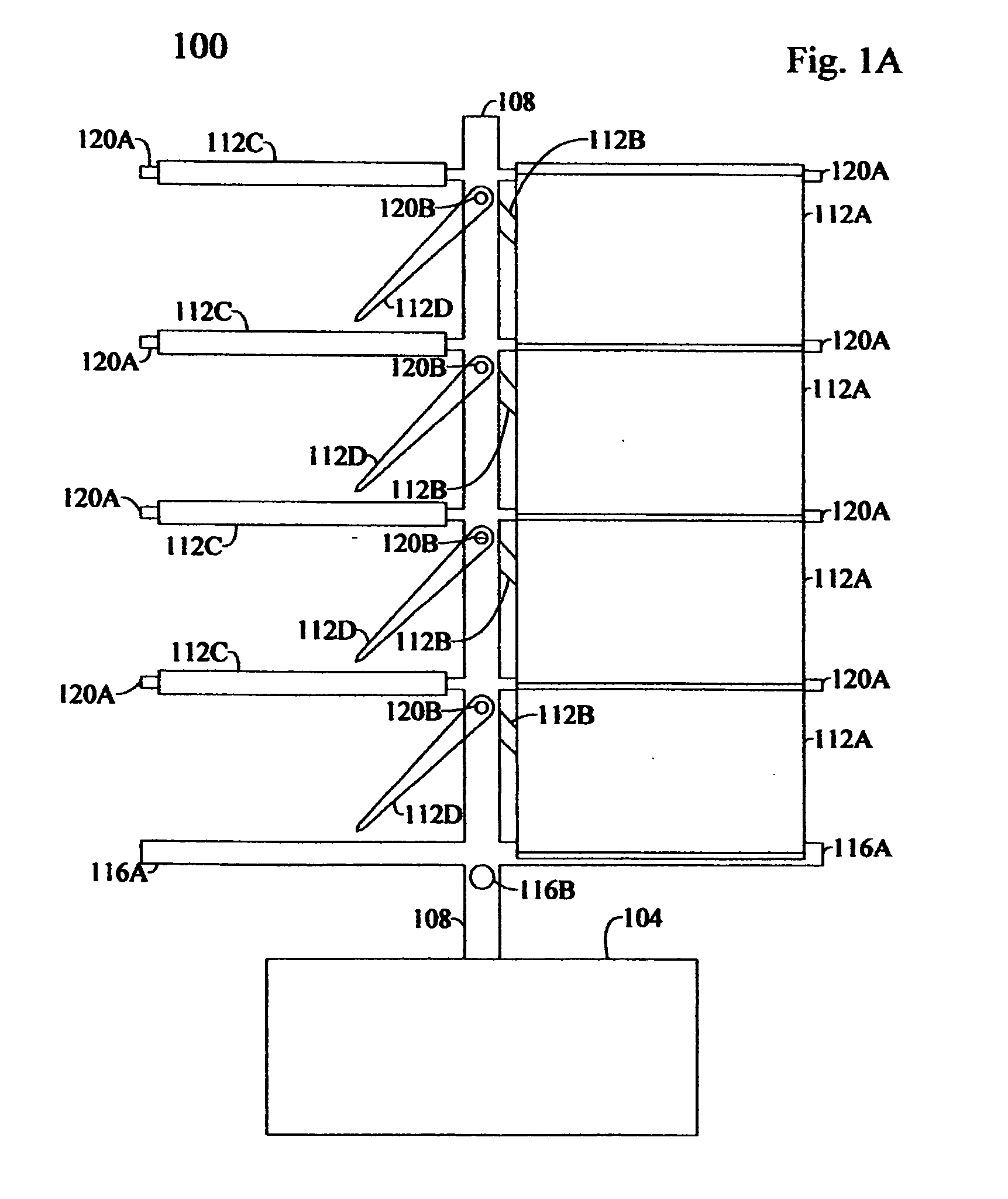
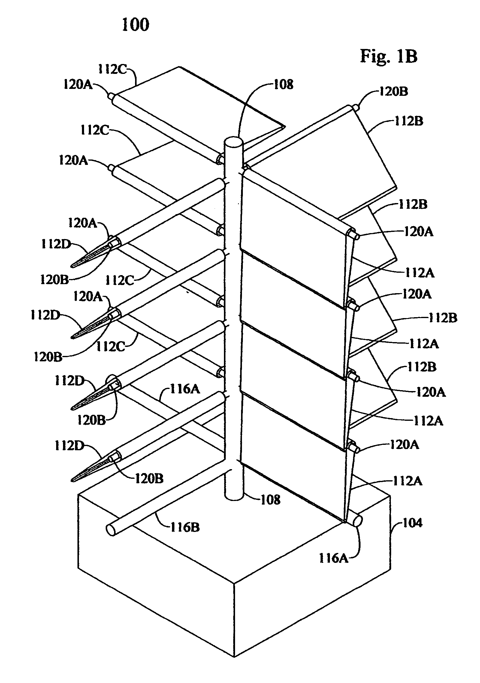
embodiment 100
[0088]The embodiment 100 has a vertical axis; a generator (not shown) connected to the vertical axis; one or more horizontal axes disposed along the vertical axis; one or more blades that are attached near each end of the horizontal axis wherein one or more blades are disposed on each side of the vertical axis, the blades are parallel to the horizontal axis, the blades are attached orthogonally relative to each other, and the blades pivot on a vertical path, wherein the blades coupled to a horizontal axis constitutes a coupled blade; and a means for restricting the pivoting of the coupled blades.
[0089]This is how the embodiment would appear if the prevailing driving force came from the direction of viewing and the orthogonal attachment of the coupled blades were as depicted in the figure. The direction of the rotation of the embodiment 100 about the vertical axis would be counterclockwise when viewed from the top if the orthogonal attachment of the coupled blades were as depicted in...
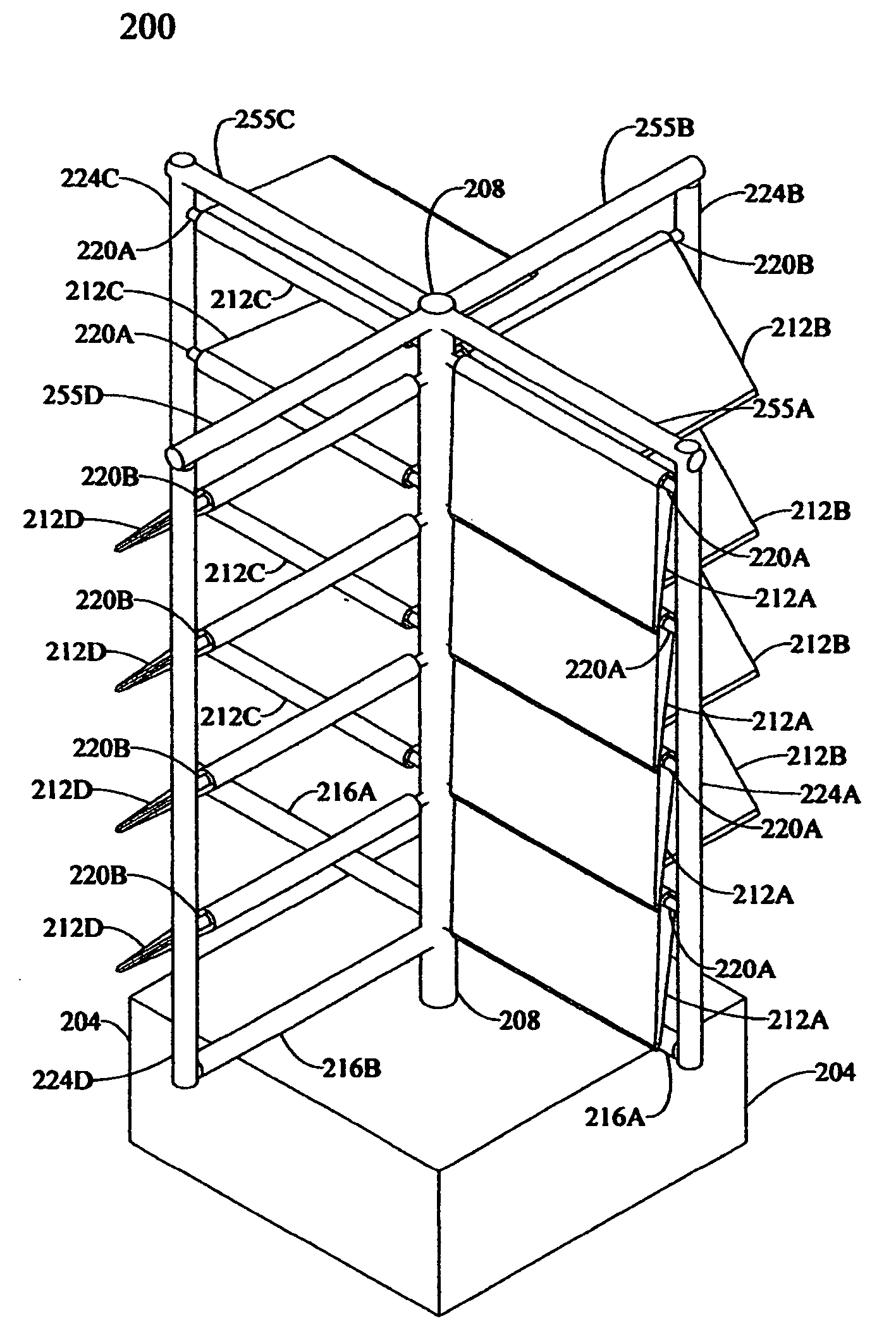
embodiment 200
[0132]Embodiment 200 has a generator housing 204 at the base of the embodiment. The generator housing 204 contains a generator (not shown) and any gears (not shown) needed for transferring a rotational force to the generator. The generator housing 204 is depicted as a broad structure to provide a solid base for the embodiment.
[0133]The rotary shaft 208 is a vertical and central shaft that rotates on a vertical axis. The rotary shaft 208 constitutes a vertical axis. The rotary shaft has several horizontal orifices that extend through the shaft. The horizontal orifices are either orthogonal or parallel to each other in this embodiment.
[0134]On the lower end of the rotary shaft 208 is a gear (not shown). The rotary shaft 208 is connected to the generator (not shown) within the generator housing 204 through a series of gears (not shown). The rotary shaft 208 drives the generator (not shown) within the generator housing.
[0135]The coupled blades (not individually labeled) are horizontally...
embodiment 300
[0165]Embodiment 300 has a generator housing 304 at the base of the embodiment. The generator housing 304 contains a generator (not shown) and any gears (not shown) needed for transferring a rotational force to the generator. The generator housing 304 is depicted as a broad structure to provide a solid base for the embodiment.
[0166]The rotary shaft 308 is a vertical and central shaft that rotates on a vertical axis. On the lower end of the rotary shaft 308 is a gear (not shown). The rotary shaft 308 is connected to the generator (not shown) within the generator housing 304 through a series of gears (not shown). The rotary shaft 308 drives the generator (not shown) within the generator housing. The upper end of the rotary shaft 308 is connected to pivot stops 316A and 316B, collectively 316.
[0167]The pivot stops 316 are horizontally disposed members. The middle portion of the pivot stops 316 are connected to the upper end of the rotary shaft 308. The pivot stop 316B is orthogonally d...
PUM
| Property | Measurement | Unit |
|---|---|---|
| Power | aaaaa | aaaaa |
Abstract
Description
Claims
Application Information