Simulations for Hydraulic Fracturing Treatments and Methods of Fracturing Naturally Fractured Formation

a hydraulic fracturing and natural fracture technology, applied in the field of natural fracture treatment methods, can solve the problems of complex network of criss-crossing fractures, inability to produce formations without hydraulic fracture stimulation, and insufficient ability of traditional single fracture models

Active Publication Date: 2008-07-31
SCHLUMBERGER TECH CORP
View PDF27 Cites 188 Cited by
  • Summary
  • Abstract
  • Description
  • Claims
  • Application Information

AI Technical Summary

Problems solved by technology

Due to the nature of very low permeability, these formations cannot produce without hydraulic fracture stimulation.
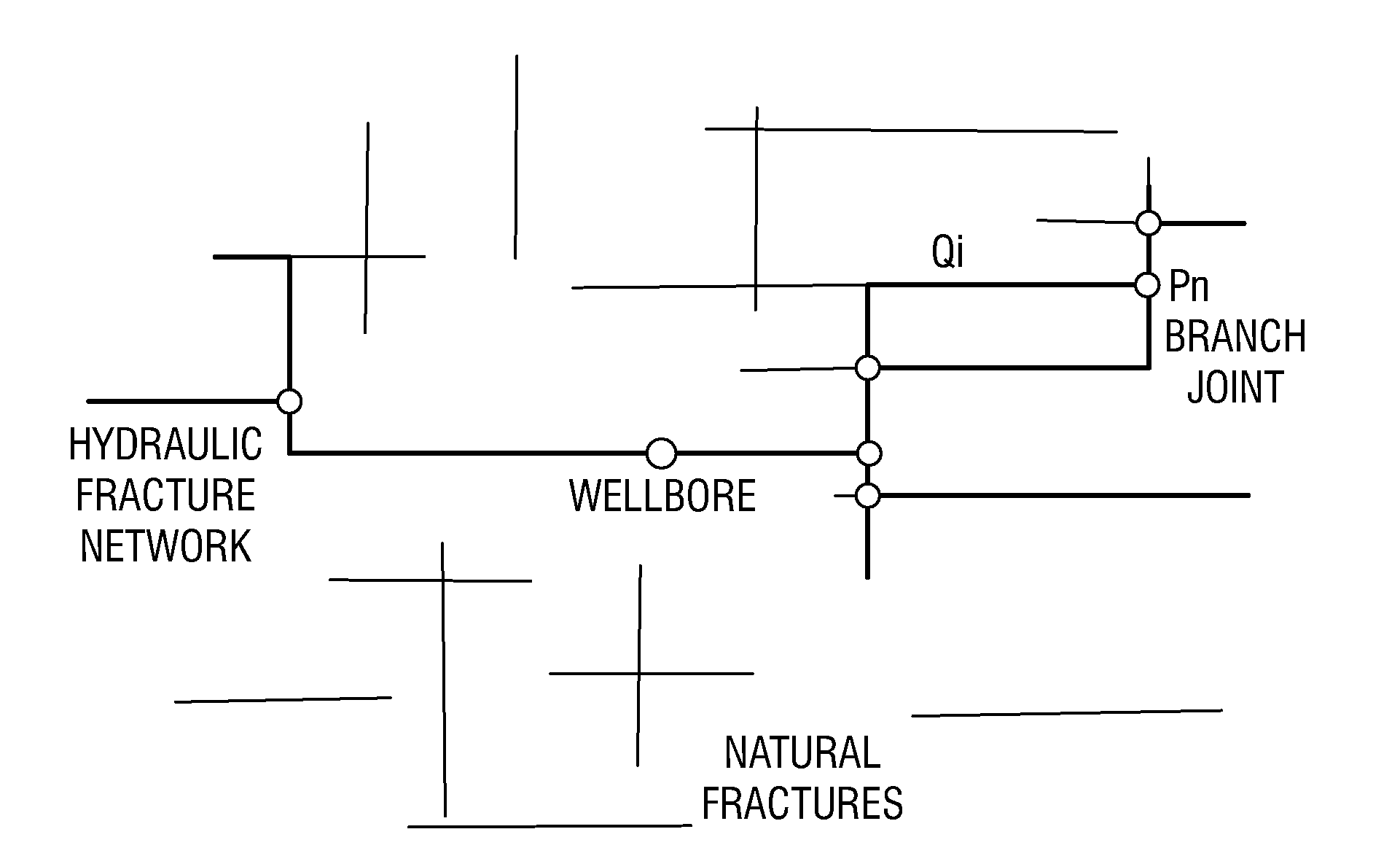
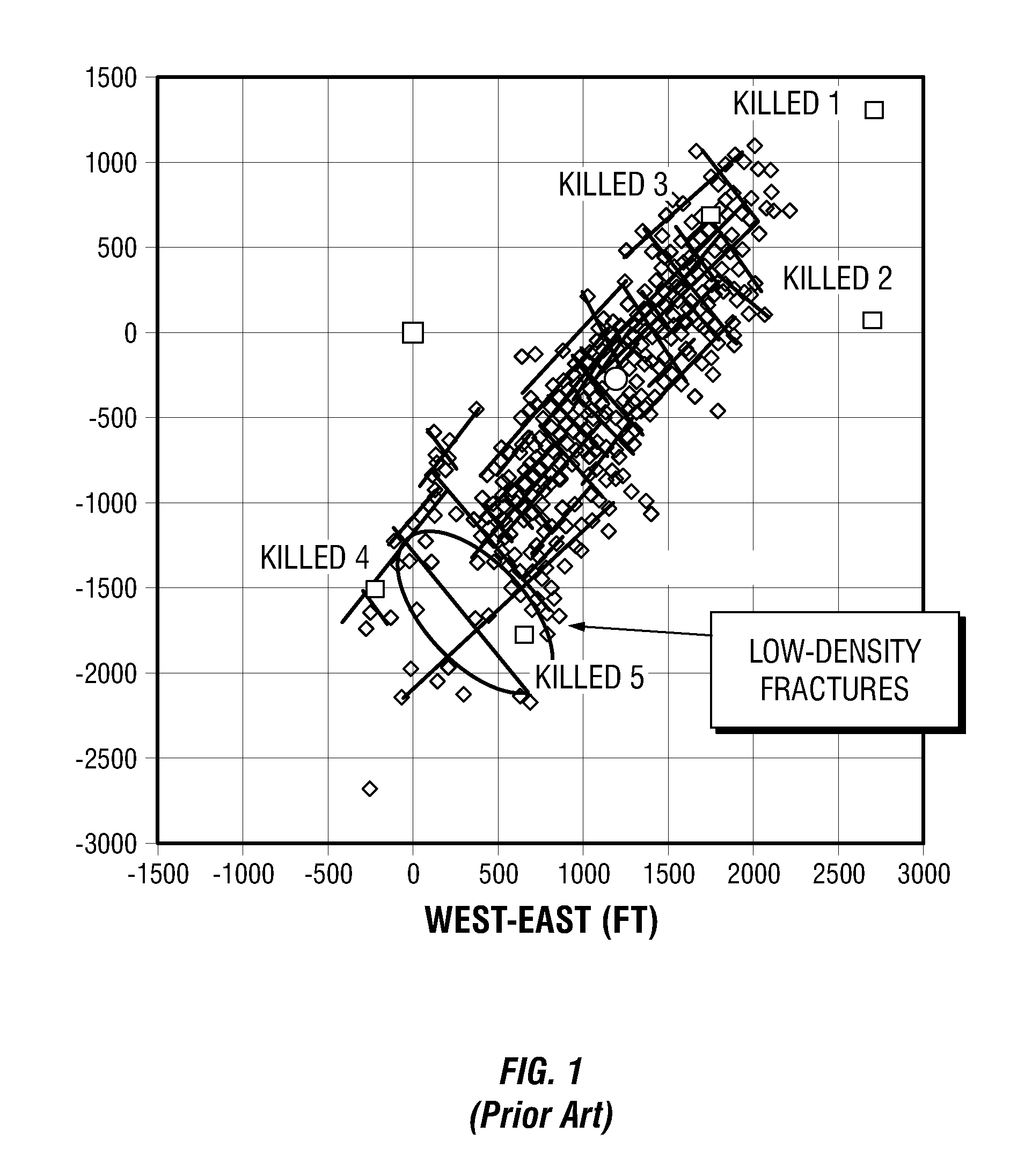
Microseismic mapping conducted during these treatments indicated that a complex network of crisscrossing fractures are created, resulting from the hydraulic fracturing fluid penetrating the existing natural fracture network.
The complex fracture geometry created during these treatments renders the traditional single fracture model completely inadequate in terms of its ability to predict the fracture size or surface area created or the sand placement.
While it has been qualitatively established that the gas production of a stimulated well is proportional to the area extent of the created fracture network based on the microseismic measurements, current design tools are not adequate for designing such jobs.
These models are computationally intensive and require long computation time, making them less suitable for daily quick job design needs.
With today's faster desktop computers, they are increasingly utilized, especially for complex reservoirs where simpler models are not adequate.
However, the fracture geometry is limited to an ellipse-like shape, and 2D approximation of the fracture surface deformation is made instead of accurately solving the much more complex 3D fracture surface deformation.
Therefore, the single fracture design model may not provide adequate prediction of the job outcome.

Method used


Image

  • Simulations for Hydraulic Fracturing Treatments and Methods of Fracturing Naturally Fractured Formation
  • Simulations for Hydraulic Fracturing Treatments and Methods of Fracturing Naturally Fractured Formation
  • Simulations for Hydraulic Fracturing Treatments and Methods of Fracturing Naturally Fractured Formation

Examples


Embodiment Construction

[0017]At the outset, it should be noted that in the development of any such actual embodiment, numerous implementation-specific decisions must be made to achieve the developer's specific goals, such as compliance with system related and business related constraints, which will vary from one implementation to another. Moreover, it will be appreciated that such a development effort might be complex and time consuming but would nevertheless be a routine undertaking for those of ordinary skill in the art having the benefit of this disclosure.

[0018]The description and examples are presented solely for the purpose of illustrating the preferred embodiments of the invention and should not be construed as a limitation to the scope and applicability of the invention. While the compositions used in methods of the invention may be described herein as comprising certain materials, it should be understood that the composition could optionally comprise two or more chemically different materials. I...


PUM

PropertyMeasurementUnit
viscosityaaaaaaaaaa
viscosityaaaaaaaaaa
concentrationaaaaaaaaaa

Abstract

A hydraulic fracture design model that simulates the complex physical process of fracture propagation in the earth driven by the injected fluid through a wellbore. An objective in the model is to adhere with the laws of physics governing the surface deformation of the created fracture subjected to the fluid pressure, the fluid flow in the gap formed by the opposing fracture surfaces, the propagation of the fracture front, the transport of the proppant in the fracture carried by the fluid, and the leakoff of the fracturing fluid into the permeable rock. The models used in accordance with methods of the invention are typically based on the assumptions and the mathematical equations for the conventional 2D or P3D models, and further take into account the network of jointed fracture segments. For each fracture segment, the mathematical equations governing the fracture deformation and fluid flow apply. For each time step, the model predicts the incremental growth of the branch tips and the pressure and flow rate distribution in the system by solving the governing equations and satisfying the boundary conditions at the fracture tips, wellbore and connected branch joints. An iterative technique is used to obtain the solution of this highly nonlinear and complex problem.

Description

CROSS REFERENCE TO RELATED APPLICATION[0001]This application claims the benefit of U.S. provisional application Ser. No. 60 / 887,008, filed Jan. 29, 2007.FIELD OF THE INVENTION[0002]This invention relates to methods of treating subterranean formations, and particularly, methods for fracture treatments performed on naturally fractured formations.BACKGROUND OF THE INVENTION[0003]The statements in this section merely provide background information related to the present disclosure and may not constitute prior art.[0004]Hydraulic fracturing is the most widely used well stimulation method to enhance hydrocarbon production from oil or gas wells. To achieve the best economical result from a hydraulic fracturing treatment, modern day fracturing treatments commonly involve an extensive design process of acquiring pertinent formation mechanical and stress data, selection of proper fracturing fluid and propping agents, and designing the pumping schedule using a design model. The fracture design...

Claims


Application Information

Patent Timeline
Patent Type & Authority Applications(United States)
IPC IPC(8): C09K8/62E21B49/00G06F17/00G06G7/00
CPCE21B43/26G06G7/50G06G7/57G06F30/28E21B43/267
Inventor WENG, XIAOWEISIEBRITS, EDUARD
Owner SCHLUMBERGER TECH CORP
Why Eureka
Try Eureka