
Shared Resources in a Chip Multiprocessor

Active Publication Date: 2008-07-31
GLOBALFOUNDRIES U S INC
View PDF4 Cites 23 Cited by
  • Summary
  • Abstract
  • Description
  • Claims
  • Application Information

AI Technical Summary

Benefits of technology

The patent describes a system with multiple processor cores and a controller that can communicate with each other. The controller can receive a read operation and return a value based on which processor core transmitted the read operation. The system also has a shared queue for storing communications from the processor cores and a fuse bank for storing values used by the processor cores. The processor cores can transmit communications at a maximum rate of one every N clock cycles. The technical effects of this system include improved performance and efficiency of processing tasks and faster data transmission between processor cores.

Problems solved by technology

Designing the additional circuitry to be efficient and to provide appropriate functionality is a challenge in CMPs.

Method used


Image

  • Shared Resources in a Chip Multiprocessor
  • Shared Resources in a Chip Multiprocessor
  • Shared Resources in a Chip Multiprocessor

Examples


Embodiment Construction

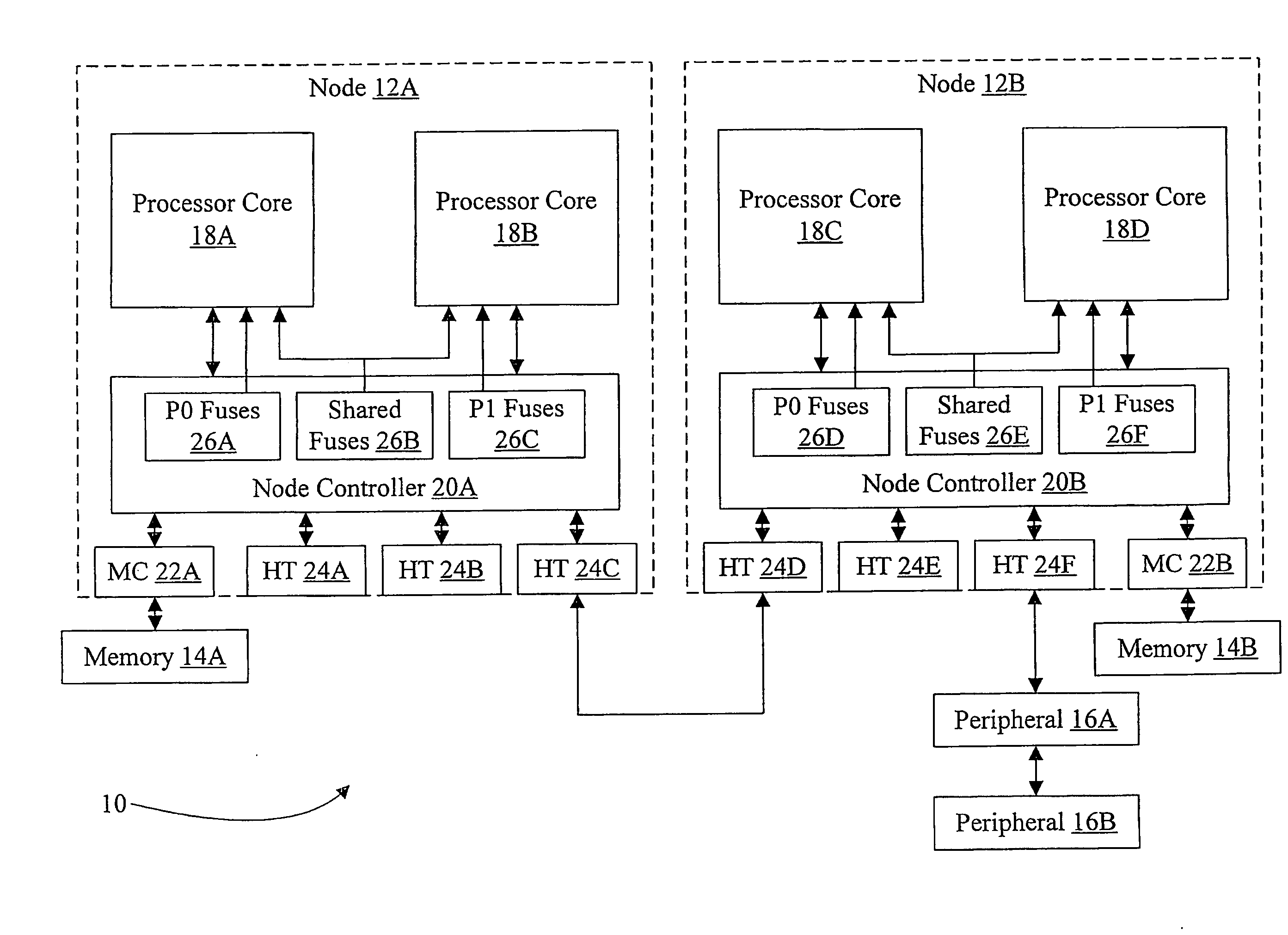
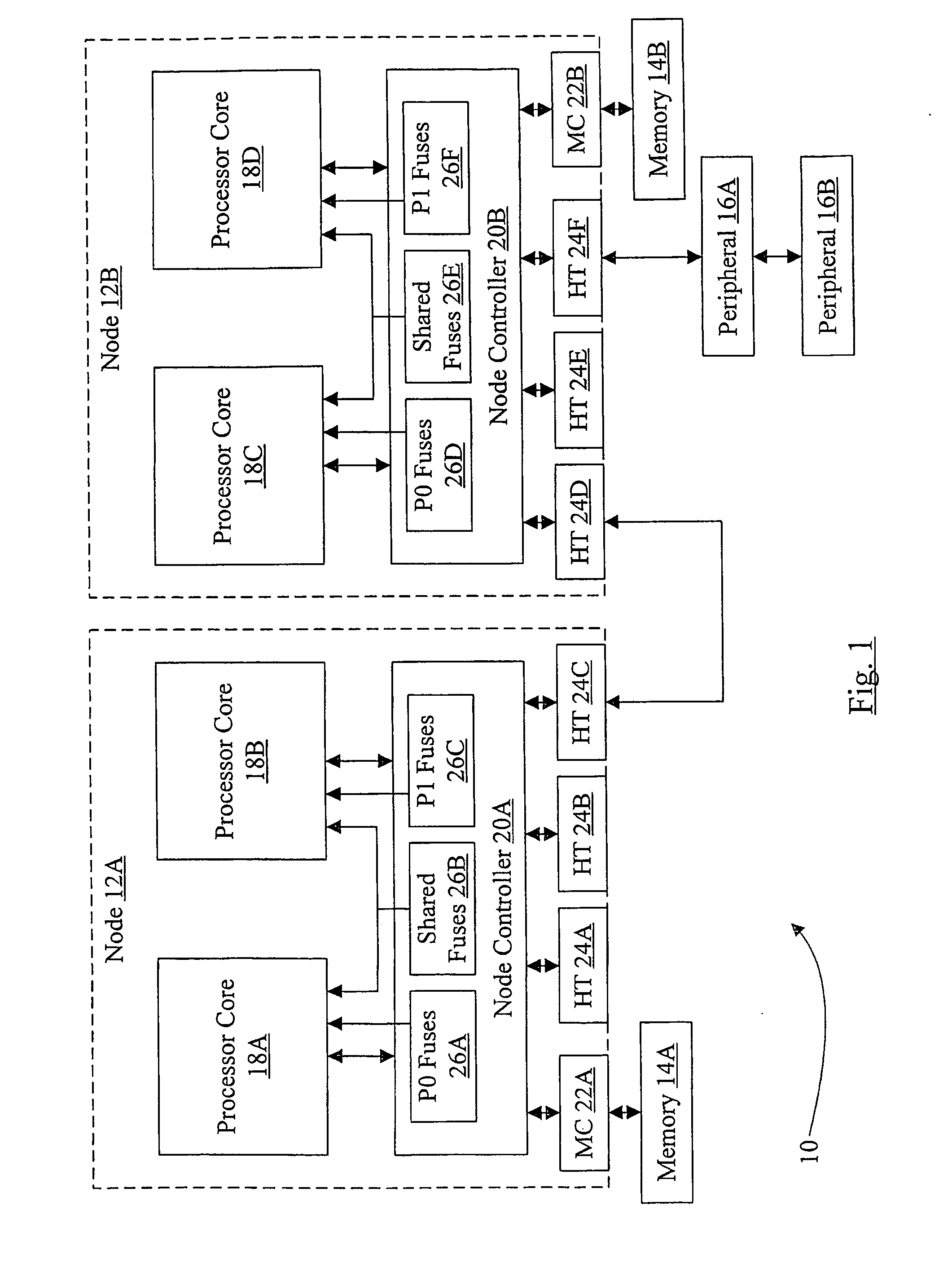
[0016]Turning now to FIG. 1, a block diagram of one embodiment of a computer system 10 is shown. In the illustrated embodiment, the computer system 10 includes nodes 12A-12B, memories 14A-14B, and peripheral devices 16A-16B. The nodes 12A-12B are coupled, and the node 12B is coupled to the peripheral devices 16A-16B. Each of the nodes 12A-12B are coupled to respective memories 14A-14B. The node 12A comprises processor cores 18A-18B coupled to a node controller 20A which is further coupled to a memory controller 22A and a plurality of HyperTransport™ (HT) interface circuits 24A-24C. The node 12B similarly comprises processor cores 18C-18D coupled to a node controller 20B which is further coupled to a memory controller 22B and a plurality of HT interface circuits 24D-24F. The HT circuits 24C-24D are coupled (via an HT interface, in this embodiment) and the HT circuit 24F is coupled to the peripheral device 16A, which is coupled to the peripheral device 16B in a daisy-chain configurati...


PUM


Abstract

In one embodiment, a node comprises a plurality of processor cores and a node controller configured to receive a first read operation addressing a first register. The node controller is configured to return a first value in response to the first read operation, dependent on which processor core transmitted the first read operation. In another embodiment, the node comprises the processor cores and the node controller. The node controller comprises a queue shared by the processor cores. The processor cores are configured to transmit communications at a maximum rate of one every N clock cycles, where N is an integer equal to a number of the processor cores. In still another embodiment, a node comprises the processor cores and a plurality of fuses shared by the processor cores. In some embodiments, the node components are integrated onto a single integrated circuit chip (e.g. a chip multiprocessor).

Description

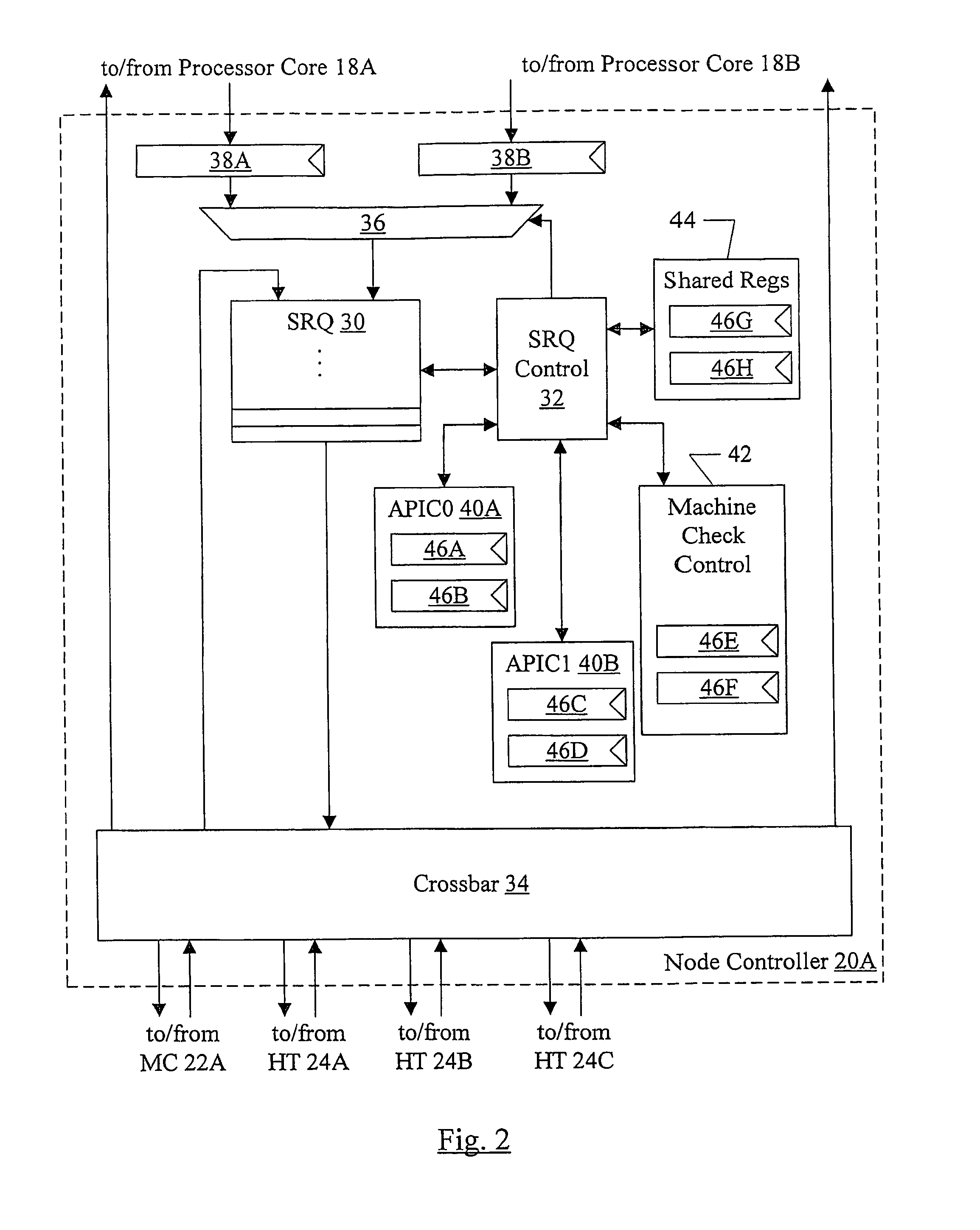
[0001]This application is a divisional application of U.S. patent application Ser. No. 10 / 957,250, filed on Oct. 1, 2004, which is incorporated herein by reference.BACKGROUND[0002]1. Field of the Invention[0003]This invention is related to the field of chip multiprocessors (CMP) and, more particularly, to sharing of resources in a CMP.[0004]2. Description of the Related Art[0005]Chip multiprocessors (CMPs) are becoming more popular in the present age. A CMP has two or more processor cores implemented on the same integrated circuit. CMPs may be a more efficient use of the millions of transistors that may be included on an integrated circuit than, for example, a more elaborate single processor.[0006]CMPs include multiple processor cores, and may include other circuitry as well. For example, circuitry to interface the processor cores to the rest of the computer system may be included. Designing the additional circuitry to be efficient and to provide appropriate functionality is a chall...

Claims


Application Information

Patent Timeline
Patent Type & Authority Applications(United States)
IPC IPC(8): G06F15/76G06F9/30
CPCG06F15/8007
Inventor HUGHES, WILLIAM A.KALYANASUNDHARAM, VYDHYANATHANBONDALAPATI, KIRAN K.MADRID, PHILIP E.ENNIS, STEPHEN C.
Owner GLOBALFOUNDRIES U S INC
Learn More