Reduced friction molds for injection molded solder processing

a technology of friction molds and injection molded solder, which is applied in the direction of foundry moulding apparatus, manufacturing tools, foundry patterns, etc., can solve the problems of increasing stress and difficulties in controlling the smoothing or radiusing process of pit edges, and reducing viscosity, so as to soften the sharp edges. , the effect of reducing the viscosity

Inactive Publication Date: 2008-08-07
GLOBALFOUNDRIES INC
View PDF13 Cites 4 Cited by
  • Summary
  • Abstract
  • Description
  • Claims
  • Application Information

AI Technical Summary

Benefits of technology

[0008]Accordingly, in order to alleviate the problems which are encountered in the presence of sharp edges in mold pits on the mold plate surface, the edges of the mold pits can be radiused or smoothed and resultingly rounded off through the intermediary of a heat treatment imparted to the glass mold plate at a temperature which is sufficiently high and over a sufficient duration of so as to enable the surface tension forces in a glass material which approaches a “near melting” or lowered viscosity condition to soften the sharp edges of the mold edge pits without substantially affecting the overall shape and volume of the mold pits. Some minor degree of alteration in shape and / or volume may be encountered, but can be precedingly compensated for during the etching of the mold pits.
[0009]Alternatively, some type of a mechanical polishing process with a compliant backing and polishing compound may be another method employed in accomplishing the smoothing of the pit edges, but may be somewhat more difficult to control and be more expensive in the implementation thereof than the process of heat treating the glass mold plate, as proposed by the present invention. Moreover, it may also be possible to utilize a surface, rather than a bulk or through-extending heat treatment, in effect, treating only the surface of the mold plate, rather than the entire thickness thereof, but this may involve an increase in stresses and difficulties in controlling the pit edge smoothing or radiusing process. Consequently, a bulk heat treatment process may be more advantageous in reducing surface texture of the glass mold plate, and thereby further reducing friction attributable to the flat areas of the glass mold plate material.
[0010]In order to attain the foregoing pit edge smoothing effect, it may be advantageous to increase the temperature of the glass mold plate up to a range of approximately 760° C., in essence, approximately 60° C. below the “softening” temperature of glass material, and to then reduce the temperature over a period of time, whereby this maximum temperature level, although well above the “annealing” temperature of the glass, may be designated as a “heat-treatment”, rather than an annealing of the glass, per se.
[0013]A substrate, which is adapted to be utilized in order to support the backside of the glass mold plate, may have to be flat and stable throughout the temperature cycle which is imparted to the mold plate, and whereby a material choice among other suitable materials may be that of quartz. There may also be provided a stable substrate material, which the glass mold plate will not adhere to at elevated temperatures, and moreover, lengthier time intervals at lower heat treatment temperatures may possibly mitigate sticking between the substrate and the glass mold plate being treated while maintaining the desired mold plate pit edge modifications.

Problems solved by technology

Alternatively, some type of a mechanical polishing process with a compliant backing and polishing compound may be another method employed in accomplishing the smoothing of the pit edges, but may be somewhat more difficult to control and be more expensive in the implementation thereof than the process of heat treating the glass mold plate, as proposed by the present invention.
Moreover, it may also be possible to utilize a surface, rather than a bulk or through-extending heat treatment, in effect, treating only the surface of the mold plate, rather than the entire thickness thereof, but this may involve an increase in stresses and difficulties in controlling the pit edge smoothing or radiusing process.

Method used


Image

  • Reduced friction molds for injection molded solder processing
  • Reduced friction molds for injection molded solder processing

Examples


Embodiment Construction

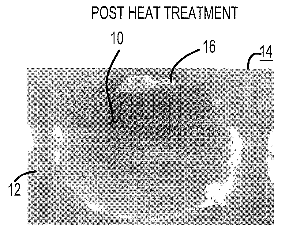
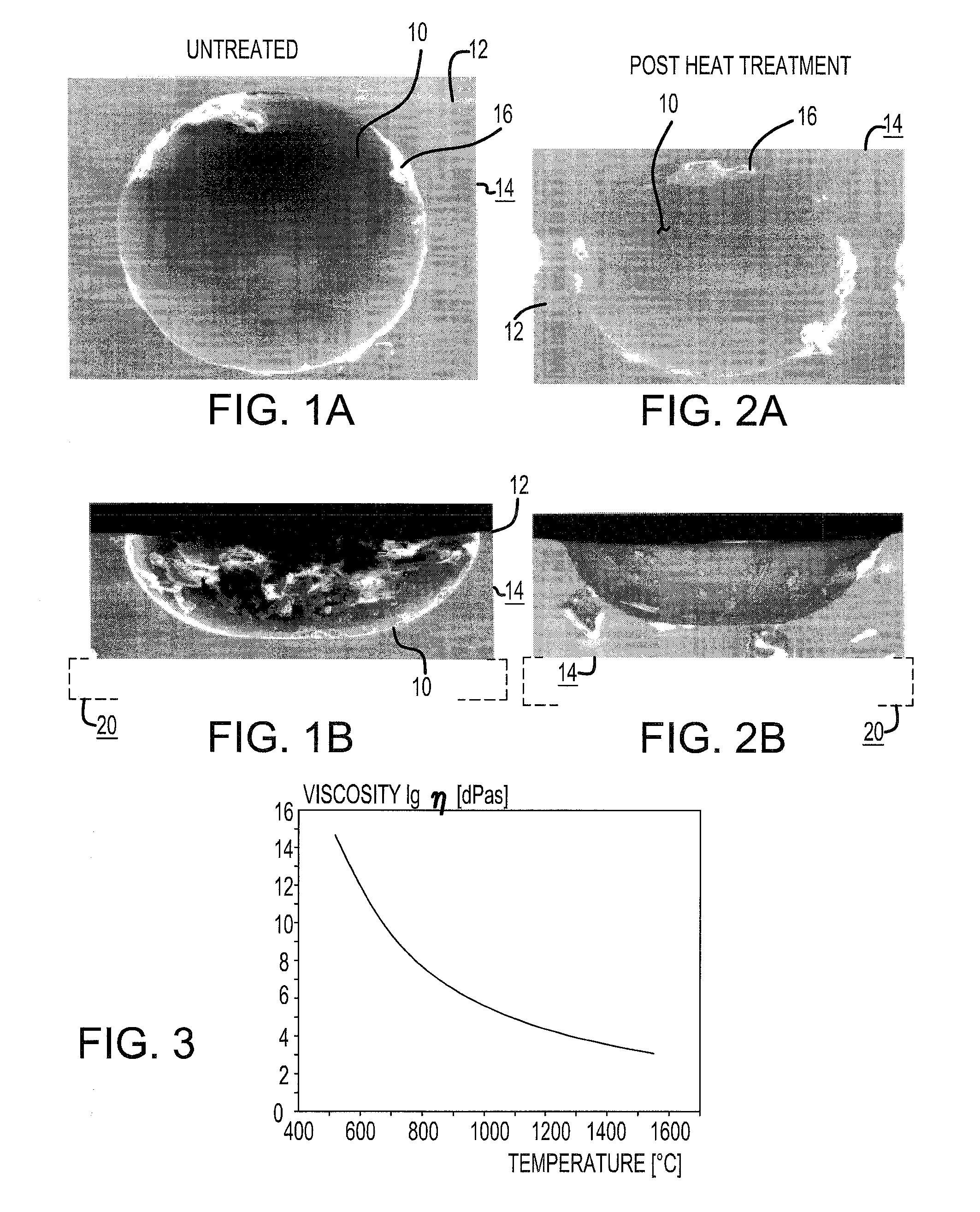
[0021]Referring to FIGS. 1A and 1B of the drawings, there is spectroscopically illustrated a typical pit or cavity 10, which has been etched into the upper surface 12 of a glass mold plate 14, and which shows the peripheral edge 16 of the pit having a relatively sharp configuration at the meeting location with the plate surface, which can readily cause undue damage to be sustained by o-rings of the apparatus and adversely affect the operation of the molding apparatus, such as be a deposition of debris and particulate contaminants of the mold plate surface and in the mold cavities. Moreover, the sharp edge 16 of the mold pit 10 may result in a shortened service life for the o-ring and also adversely affect the functioning of the fill head of the mold apparatus.

[0022]As illustrated in FIGS. 2A and 2B of the drawings, wherein the glass mold plate 14 has been heat-treated at the temperatures such as from about 740° C. to about 800° C. for a predetermined period of time, preferably withi...


PUM

PropertyMeasurementUnit
softening temperatureaaaaaaaaaa
temperatureaaaaaaaaaa

Abstract

A process of reducing friction, which is encountered in molds utilized in injection molded, solder processing, and wherein glass mold plates have mold pits etched therein. The mold pates are subjected to a heat treatment so as to smooth or round-off sharp edges along the periphery of the mold pits.

Description

BACKGROUND OF THE INVENTION[0001]1. Field of the Invention[0002]The present invention relates to a process of reducing friction, which is encountered in molds utilized in injection molded solder processing.[0003]2. Background Art[0004]In the fabrication of mold plates, which are utilized for purposes of injection molded solder processes, particularly those employed to produce semiconductor chip connection processes, for instance, such as for the controlled collapse chip connect new process (C4NP), the normally glass material mold plates are generally produced utilizing an etching process which causes the surface of the mold plates to be provided with mold pits or cavities. These etched mold pits in the mold plate surfaces are frequently encountered in possessing sharp edges, whereby the sharp edges have a tendency to abrade the mold fill head o-rings of the mold apparatus. This may cause debris from the o-rings to be located on or embedded in the mold plate, which is equipped with p...

Claims


Application Information

Patent Timeline
Patent Type & Authority Applications(United States)
IPC IPC(8): B22D11/07
CPCH05K2203/0113H05K3/3457
Inventor SCHULTZ, MARK D.
Owner GLOBALFOUNDRIES INC
Why Eureka
Try Eureka