Plasma spraying device and method

a technology of spraying device and spraying method, which is applied in the direction of gas-filled discharge tube, manufacturing tools, and solventing apparatus, etc., can solve the problems of high homogeneity of flowable materials, and achieve the effects of increasing velocity pressure, static pressure reduction, and high homogeneity

Active Publication Date: 2008-08-07
PLASMA SURGICAL INVESTMENTS
View PDF99 Cites 38 Cited by
  • Summary
  • Abstract
  • Description
  • Claims
  • Application Information

AI Technical Summary

Benefits of technology

[0020]In the plasma spraying device, the high pressure portion of the plasma channel is formed by at least one, but preferably two or more, intermediate electrodes. This enables the plasma flow that reaches the throttling portion to be sufficiently heated to achieve a high level of homogeneity of a given flowable material, such as powder, injected into the plasma flow. The low pressure portion of the plasma channel is formed by at least one, but preferably two or more, intermediate electrodes. This enables sufficient heating of the flowable material for a given spraying application after the flowable material is injected into the plasma flow.
[0021]During operation, a plasma generating gas is supplied to the plasma channel. As the gas flows through the plasma channel, it is heated by an electric arc formed between the cathode and the anode. The temperature increase of the electric arc results in gas ionization and plasma formation. The static pressure of the plasma in the high pressure portion of the plasma channel is relatively high. As the plasma passes through the throttling portion, its velocity pressure increases and the static pressure decreases. The increase in the velocity pressure may accelerate the plasma flow to supersonic speeds. At the end of the throttling portion closest to the anode, the static pressure of the plasma is at its minimum. The flowable material is injected into the plasma flow in the low pressure portion, which, due to the low static pressure of the plasma, requires minimal pressure.

Problems solved by technology

The injection of the flowable material in the described device results in a high level of homogeneity of the flowable material because the plasma is sufficiently heated while passing through the high pressure portion.

Method used


Image

  • Plasma spraying device and method
  • Plasma spraying device and method
  • Plasma spraying device and method

Examples


Embodiment Construction

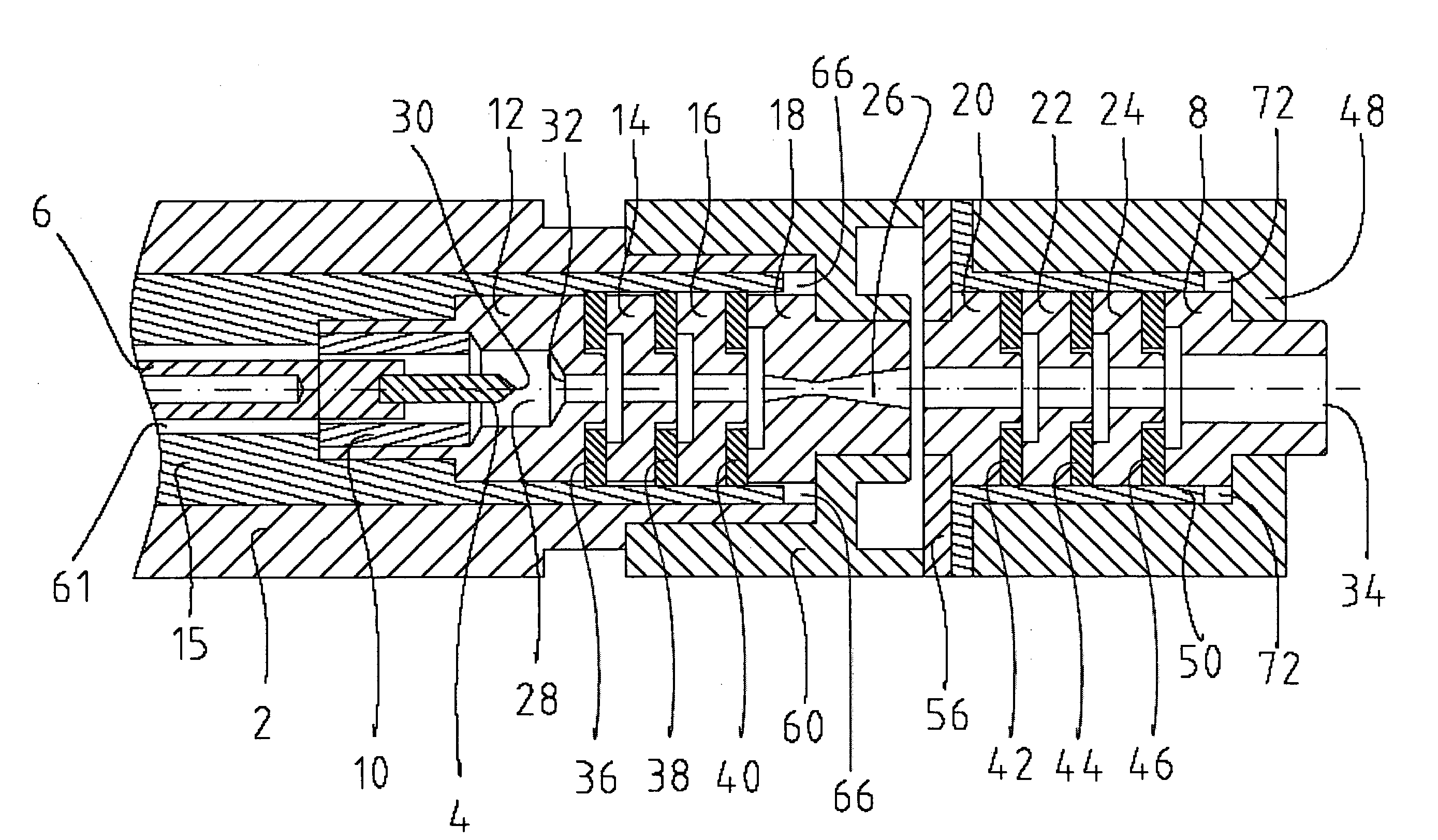
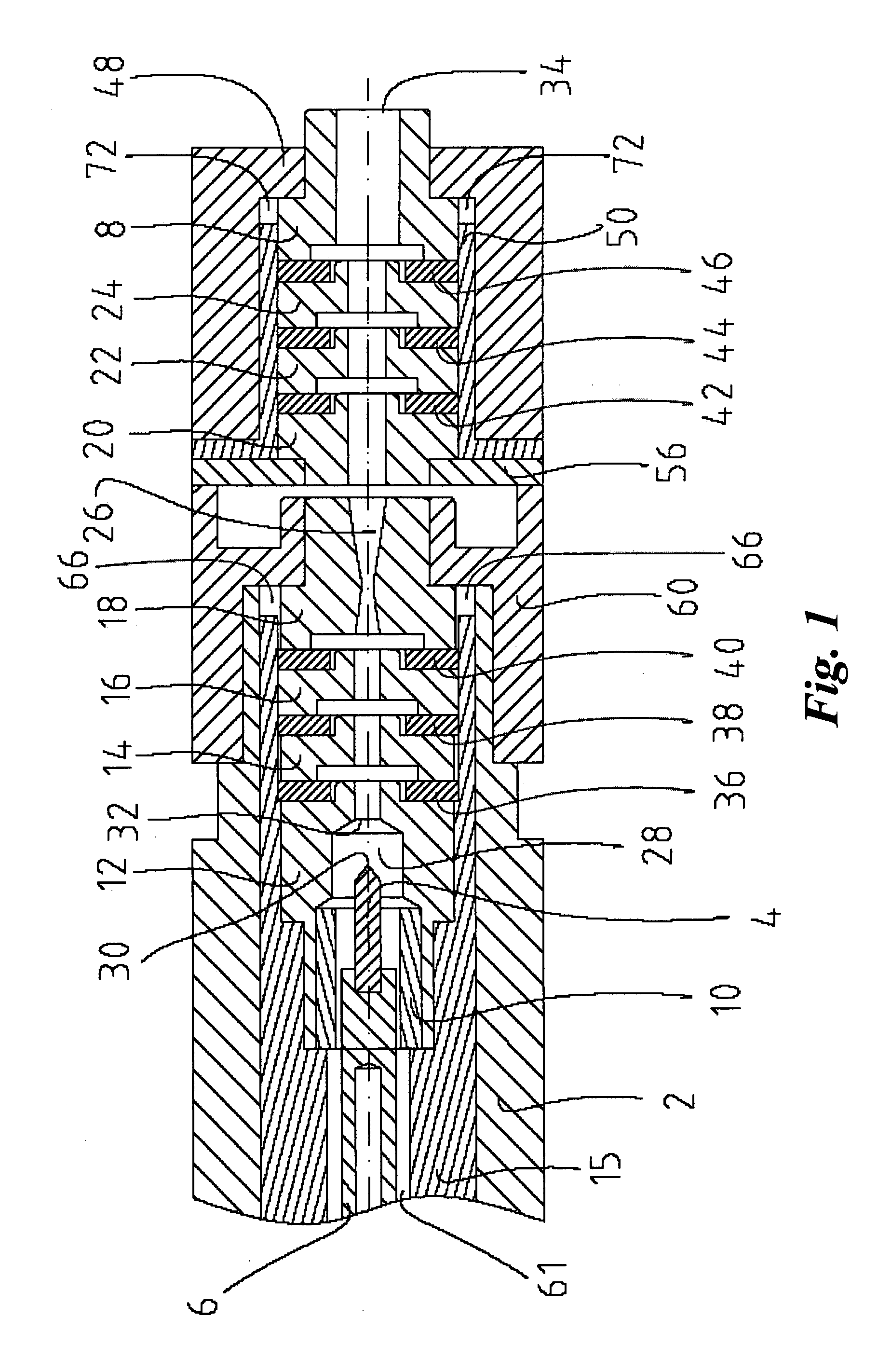
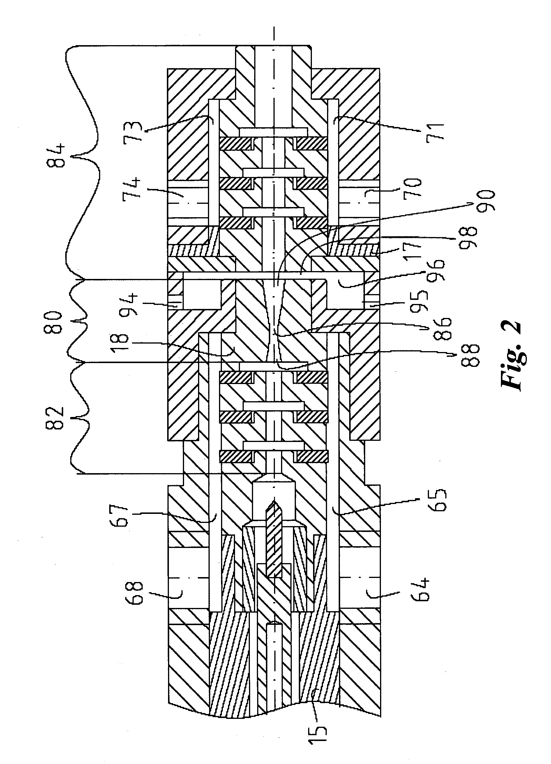
[0031]FIGS. 1 and 2 illustrate one embodiment of a plasma-spraying device according to the invention. The embodiment depicted in FIGS. 1 and 2 is a powder spraying device with a single flowable material injector. However, it should be understood that this is an exemplary embodiment and is not meant to limit the scope of the invention to the use of a powder or to the use of a single flowable material or a single injector. For purposes of this disclosure, the expression “flowable material” is defined as any material that flows in a vessel under pressure. Flowable materials include, but are not limited to, liquids, gases, or particles of solid materials carried by a fluid. The term “powder” in the present disclosure should be understood as small particles of a material that can be carried by a fluid, such as a gas; for the purposes of this disclosure, a “powder” is a flowable material. Another variation of a flowable material is a solution of powder particles, such as nanoparticles, in...


PUM

PropertyMeasurementUnit
electric fieldaaaaaaaaaa
velocityaaaaaaaaaa
velocityaaaaaaaaaa

Abstract

A device and a method for plasma spraying are disclosed. The device comprises, a cathode, an anode, a plasma channel formed by the anode and intermediate electrodes, and one or more flowable material injectors. The plasma channel has a throttling portion that divides the plasma channel into a high pressure portion near the cathode formed by at least one intermediate electrode and a low pressure portion near the anode. During operation, a plasma generating gas is heated by the arc maintained between the cathode and the anode, forming plasma. When the plasma passes through the throttling portion, its speed increases to a supersonic speed, and at the same time its static pressure drops. Flowable materials are injected in the plasma flow in the low pressure portion. The particles in the flowable materials are heated by the plasma and the resultant heated particles and plasma are output from the outlet of the plasma channel.

Description

FIELD OF INVENTION[0001]The present invention is in the field of plasma spray technology. In particular a plasma generating device and a method for spraying flowable materials are disclosed.BACKGROUND[0002]Plasma spraying devices are used for spraying various flowable materials, such as powdered materials (or simply powders), in a number of applications, including, for example, in connection with coating applications. Such devices typically comprise a cathode, an anode, and a plasma channel extending between the cathode and through the anode. During operation, a plasma-generating gas is supplied to the plasma channel. The electrical arc formed between the cathode and the anode heats the gas flowing through the plasma channel, forming a plasma flow (sometimes also called a plasma stream or plasma jet). The plasma flow exits the device through an outlet in the anode at the end of the plasma channel. Several different types of plasma spraying devices are known. These types may be chara...

Claims


Application Information

Patent Timeline
Patent Type & Authority Applications(United States)
IPC IPC(8): B23K9/00
CPCC23C4/127Y02T50/67H05H2001/3452H05H1/34C23C4/134H05H1/3452Y02T50/60
Inventor SUSLOV, NIKOLAY
Owner PLASMA SURGICAL INVESTMENTS
Why Eureka
Try Eureka