Method for Manufacturing Pipe-Type Woven Carbon Fibers and Carbon Fiber Heating Lamp Using The Pipe-Type Woven Carbon Fibers

a technology of woven carbon fibers and heating lamps, which is applied in the field of carbon fiber heating lamps, can solve the problems of easy deformation of filaments, easy damage of filaments, and low durability of lamps, and achieve the effects of easy adjustment of resistance values, increased carbon fiber bundles, and high durability

Active Publication Date: 2008-08-07
LG ELECTRONICS INC
View PDF7 Cites 6 Cited by
  • Summary
  • Abstract
  • Description
  • Claims
  • Application Information

AI Technical Summary

Benefits of technology

[0023]As described above, according to the present invention, a carbon fiber pipe is woven to have a hollow part in a central position. In this way, the hollow part functions to absorb shocks and resist deformation. Thus, a heating lamp using the carbon fiber pipe has high durability. Further, a large quantity of carbon fibers or carbon cores is woven to have a circular shape. As such, since a large quantity of carbon fibers is used, it is easy to adjust the resistance value. Meanwhile, the prior art is problematic in that it has tended to increase the number of carbon fiber bundles, so that it is not easy to weave, and carbon fiber bundles are easily separated from each other, thus the defect rate is high. Conversely, according to this invention, the carbon fiber pipe is manufactured to have the shape of a cylinder which is hollow, so that it is easy to manufacture, and the same effect when extending the length of carbon fiber is achieved. Thus, even if carbon fiber is short, it has a high resistance value, thus allowing a heating lamp having high power to be manufactured. Further, even though carbon fiber is short, a high resistance value may be obtained merely by increasing the diameter of the carbon fiber pipe. Therefore, various designs of heating lamps may be manufactured.
[0024]Moreover, when heat is emitted through the hollow part, the inner and outer surfaces of the carbon fiber pipe maintain a constant temperature, thus preventing deformation, therefore enhancing durability.
[0025]Further, according to the invention, the carbon fiber pipe is knitted using carbon fibers alternated with general fibers, and heat-resistance coating is applied to the knitted carbon fiber pipe. Afterwards, when a burning process is executed, the general fibers burned out, and a coating layer is sintered on the surface of the carbon fibers, thus maintaining a shape and having a restoring force. Thereby, when the heating lamp is in use, the durability of the heating lamp is increased.

Problems solved by technology

However, the conventional lamp operated as described above is problematic in that the filament may be easily damaged by external impacts, and the filament may be easily deformed due to generated heat.
That is, the lamp is not durable.
Further, the conventional lamp is problematic in that a high cost is required to install the filament, so that the lamp is expensive.
However, the carbon fibers are used as a heating source of the sheet-type heating element, which is designed to generate a temperature ranging from about 50° C. to about 70° C. If the temperature exceeds 70° C., there is a danger of fire, and the sheet-type heating element may be oxidized by oxygen, so that the durability of the sheet-type heating element will be remarkably reduced.
However, the technology of forming a certain bundle of carbon fibers to determine the resistance value and thus provide a desired power, the technology of securing carbon fibers to terminals, and the technology of bundling carbon fibers are below a desired level.
Thereby, it is difficult to industrialize the heating lamp.
In such a heating element, a desired carbon fiber 6 is selected and a desired number of carbon fiber bundles is used to provide a desired resistance value and thus output a desired power W. However, the heating element is problematic in that it is complicated to bind the carbon fibers 6 with the carbon yarns 7, and the carbon core must be impregnated into liquid resin to prevent the tied carbon yarns 7 from being removed, as necessary.
The technology is problematic in that it is difficult to locate the filament 10 at a central position in the vacuum hermetic tube 3, so that the spacers 13 must also be installed.
However, such a technology is problematic in that there is no component for supporting the heating element 2a, so that the heating element 2a may sag and come into contact with the inner wall of the hermetic tube 3.
Due to such contact, overheating occurs, so durability is reduced, and thereby it is difficult to industrialize the heating lamp.
However, such a heating element is based on a band-shaped heating element, so that it is limitedly able to maintain its elastic force, and it is difficult to produce the heating element as a product.
Further, as shown in FIG. 3, the spacers must be installed at regular intervals, so that marketability is poor.

Method used


Image

  • Method for Manufacturing Pipe-Type Woven Carbon Fibers and Carbon Fiber Heating Lamp Using The Pipe-Type Woven Carbon Fibers
  • Method for Manufacturing Pipe-Type Woven Carbon Fibers and Carbon Fiber Heating Lamp Using The Pipe-Type Woven Carbon Fibers
  • Method for Manufacturing Pipe-Type Woven Carbon Fibers and Carbon Fiber Heating Lamp Using The Pipe-Type Woven Carbon Fibers

Examples


Embodiment Construction

[0039]Hereinafter, the preferred embodiments of the present invention will be described in detail with reference to the accompanying drawings.

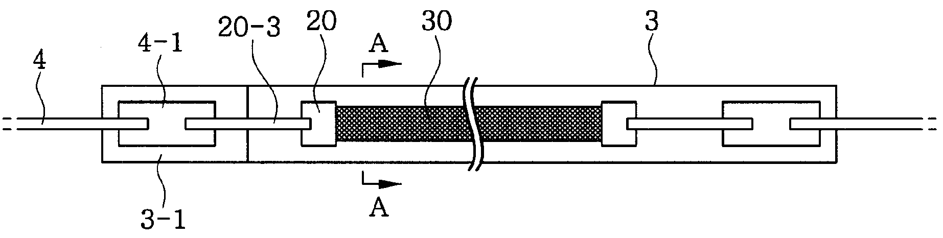
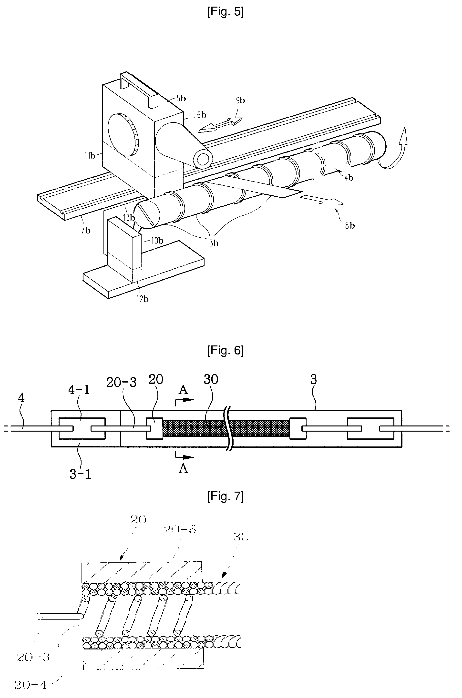
[0040]FIG. 6 is a plan view of the present invention, FIG. 7 is a sectional view of a support terminal, FIG. 8 is an enlarged sectional view taken along line A-A of FIG. 6, and FIG. 9 is an enlarged sectional view showing another example of FIG. 6. A heating element comprises a carbon fiber pipe 30 which has a cylindrical shape formed by twisting several strands of carbon fibers. Support terminals 20 for conducting electricity are provided on the opposite ends of the carbon fiber pipe 30. Each support terminal 20 is secured via a heat-resistant intermediate terminal 20-3 to a corresponding electrode piece 4-1 which is secured to an outer lead wire 4 in such a way to conduct electricity. In this case, each of the intermediate terminal 20-3 and electrode piece 4-1 may be preferably made of molybdenum having superior heat resistance.

[0041]Referen...


PUM

PropertyMeasurementUnit
temperatureaaaaaaaaaa
resistanceaaaaaaaaaa
lengthaaaaaaaaaa

Abstract

Disclosed herein are a method of manufacturing a carbon-fiber pipe which is hollow and has a net shape, by knitting carbon fibers and general fibers, applying carbon or ceramic, and heating to burn the general fibers, and a carbon fiber heating lamp using the carbon-fiber pipe. The heating lamp includes a vacuum glass tube, a tubular carbon fiber pipe (30) which is knitted using carbon fiber (6) and general fiber as a raw material and has a hollow part, and a heating element. The heating element comprises the hollow tubular carbon fiber pipe (30) which has a predetermined length and is installed in the vacuum glass tube, and generates heat using power supplied from an exterior through both terminals provided on an outer portion of the vacuum glass tube.

Description

TECHNICAL FIELD[0001]The present invention relates, in general, to a carbon fiber heating lamp and a method of manufacturing a carbon-fiber pipe therefor and, more particularly, to a method of manufacturing a carbon-fiber pipe which is hollow and has a net shape, by knitting carbon fibers and general fibers as raw materials, applying carbon or ceramic, and heating to burn the general fibers, and a carbon fiber heating lamp using the carbon-fiber pipe.BACKGROUND ART[0002]Generally, lamps include a vacuum glass tube and a filament installed in the glass tube. The lamps are typically classified into illumination lamps, which generate light when current flows in the filament, and heating lamps which generate heat in the filament. Such a lamp is manufactured by installing a filament in a vacuum glass tube and installing terminals on the opposite ends of the glass tube to connect the filament to the outside. In a detailed description, the lamp is manufactured by installing the tungsten fi...

Claims


Application Information

Patent Timeline
Patent Type & Authority Applications(United States)
IPC IPC(8): H05B3/14B29C35/00B29C67/00
CPCH05B3/145H05B3/009
Inventor CHO, JEONG-YOUN
Owner LG ELECTRONICS INC
Why Eureka
Try Eureka