Heating device and image formation apparatus

a technology of image formation apparatus and heating device, which is applied in the direction of electrographic process apparatus, instruments, optics, etc., can solve the problem of shortened life of fixing film, achieve the effect of ensuring the uniform dispersibility of lubricant and smooth spreading of lubricant agen

Inactive Publication Date: 2008-08-07
COPYER
View PDF3 Cites 32 Cited by
  • Summary
  • Abstract
  • Description
  • Claims
  • Application Information

AI Technical Summary

Benefits of technology

[0011]According to a heating device according to the present invention having such a structure, on the sliding surface of the heating support member positioned in a downstream side in the film body moving direction where the heating temperature is comparatively high and the fluidity of the lubricant agent is increased, the fluid guiding groove which uniformly guides and spreads the lubricant agent is provided. Therefore, the lubricant agent is well dispersed and uniformly spread over the entire region from the both-end regions to the center region of the heating support member and the film body, thereby well maintaining the slidability of the film body over a long period of time.
[0013]As described above, according to the present invention, by a simple structure, uniform spreading of the lubricant agent in the direction orthogonal to the film body moving direction is facilitated, the life of the apparatus can be elongated by eliminating lubricant agent leakage, generation of abnormal noise due to contamination due to lubricant agent leakage or lubricant agent shortage can be prevented, and the reliability of the heating device and image formation apparatus can be significantly improved with low cost.
[0015]In the heating device according to the present invention, when a structure in which the inclination angles of the plurality of fluid guiding grooves are set to be mutually different or a structure in which the inclination angles of the plurality of fluid guiding grooves are successively increased and varied in the direction orthogonal to the moving direction is employed, the fluid guiding grooves are formed so as to have the inclination angles corresponding to the temperature distribution in the longitudinal direction, in other words, the level of the fluidity of the lubricant agent, thereby more reliably maintaining the uniform dispersibility of the lubricant agent.
[0016]In the heating device according to the present invention, when a structure in which disposition intervals of the plurality of fluid guiding grooves are successively varied in the direction orthogonal to the moving direction of the film body or a structure in which the inclination angles and disposition intervals of the plurality of fluid guiding grooves are set to be mutually different in a center-side region and end-side region in the direction orthogonal to the moving direction of the film body is employed, the fluid guiding grooves are formed so as to have disposition intervals corresponding to the temperature distribution in the longitudinal direction, in other words, the level of the fluidity of the lubricant agent, thereby more reliably maintaining the uniform dispersibility of the lubricant agent.
[0017]In the heating device according to the present invention, when a structure in which a bottom surface portion of the fluid guiding groove is formed to be a curved surface is employed, spreading of the lubricant agent is more smoothly performed.

Problems solved by technology

Therefore, the edge of the fluid guiding groove and the inner surface of the fixing film do not strongly abut each other, and the life of the fixing film is not shortened due to damaged inner surface of the fixing film like conventional cases.

Method used


Image

  • Heating device and image formation apparatus
  • Heating device and image formation apparatus
  • Heating device and image formation apparatus

Examples


Embodiment Construction

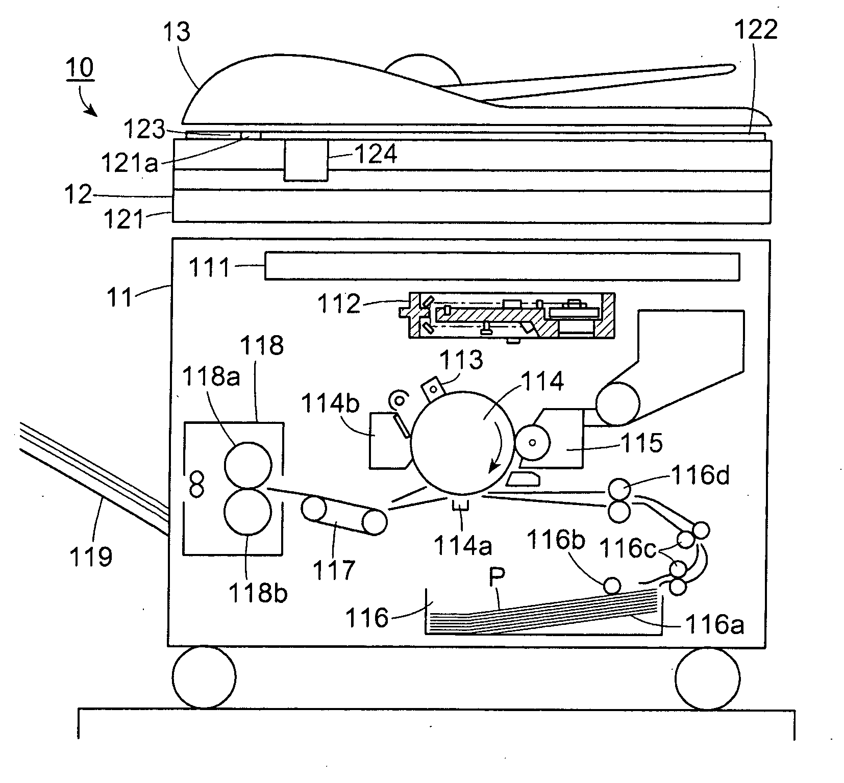
[0029]Hereinafter, embodiments in which the present invention is applied to a heating fixing device of a copy machine will be described in detail based on drawings. First of all, as shown in FIG. 1, a whole structure of a copy machine serving as an image formation apparatus will be described.

[0030]The entirety of a copy machine 10 shown in FIG. 1 has a printer unit (apparatus main body unit) 11 which performs image formation operations with respect to recording sheets P serving as heating target materials, an image reading device 12 set at an upper position of the printer unit 11, and an automatic document feeding device (ADF) 13 which automatically feeds documents to the image reading device 12.

[0031]When image information of documents read by the image reading device 12 is input to a controller 111 disposed in the printer unit (apparatus main body unit) 11, it is fed to a laser beam scanner 112 as image signals. A scanning beam emitted from the laser beam scanner 112 irradiates a ...


PUM


Abstract

On a sliding surface of a heating support body positioned in a downstream side in a film body moving direction wherein the heating temperature is comparatively high and the fluidity of a lubricant agent is good, fluid guiding grooves which uniformly disperse the lubricant agent are provided, thereby well dispersing the lubricant agent over the entire region from a center region to both-end regions of the heating support body and the film body and maintaining good slidability of the film body over a long period of time.

Description

TECHNICAL FIELD[0001]The present invention relates to a heating device and an image formation apparatus configured to heat a heating target material with interposition of a film body pressure-contacted with a heating body.BACKGROUND ART[0002]Generally, a heating device having a structure in which a heating target material is pressure-contacted with an arbitrary heating body with interposition of a film body therebetween and the heating target material is moved with the film body and heated at the same time has been used in various apparatuses. For example, various image formation apparatuses such as a printer using an electrophotographic method, a copy machine, and a fax machine employ a heating fixing device of a contact heating type which performs fixation of unfixed toner images transferred from an image carrier such as a photoconductive drum to a recording material side. In the heating fixing device, a film heating fixation method in which the recording material is heated via a ...

Claims


Application Information

Patent Timeline
Patent Type & Authority Applications(United States)
IPC IPC(8): G03G15/20
CPCG03G2215/00493G03G15/2025G03G15/6591G03G2215/2093
Inventor KATO, WATARU
Owner COPYER
Why Eureka
Try Eureka