Ag-based reflection film and method for preparing the same

a reflection film and ag-based technology, applied in the direction of superimposed coating process, natural mineral layered products, vacuum evaporation coating, etc., can solve the problems of low corrosion resistance of ag or ag-alloy thin film, reduced reflectance thereof, inferior adhesion ability to substrates or adhesive properties of thin films, etc., to achieve improved capping layer transmittance, high reflectance, and significant stabilization

Inactive Publication Date: 2006-03-30
ULVAC INC +1
View PDF9 Cites 22 Cited by
  • Summary
  • Abstract
  • Description
  • Claims
  • Application Information

AI Technical Summary

Benefits of technology

[0023] After the quite thin capping layer is thus formed on the Ag or Ag-alloy thin film according to the foregoing procedures, the resulting assembly is preferably subjected to an annealing treatment in the air, in a vacuum or an inert gas atmosphere. Such an annealing treatment after the formation of such a film is not necessarily carried out, but the annealing treatment would permit the improvement of the transmittance of the capping layer and the progress of the crystallization of the Ag or Ag-alloy thin film and accordingly, the resulting film is considerably stabilized.
[0024] The Ag-based reflection film according to the present invention never undergoes any deterioration even under such severe conditions for the corrosion resistance test carried out, for instance, in an atmosphere containing hydrogen sulfide and can maintain a high reflectance over an extremely long period of time and the method of the present invention permits the preparation of such an excellent Ag-based reflection film.

Problems solved by technology

However, it has been known that this Ag or Ag-alloy thin film suffers from a problem of low corrosion resistance.
More specifically, the Ag or Ag-alloy thin film undergoes discoloration due to the reaction with sulfur- and / or chlorine-containing components present in the air or the surrounding atmosphere, the reflectance thereof is in turn reduced and the thin film is likewise inferior in the ability to adhere to a substrate or the adhesive properties.
However, a film of such an alloy does not always have satisfactorily high corrosion resistance in an atmosphere containing hydrogen sulfide and it has insufficient adhesion to a substrate.
For this reason, the thickness distribution of each layer constituting the multi-layered structure should be made uniform and this would correspondingly increase the production cost of the light-reflection layer.

Method used


Image

  • Ag-based reflection film and method for preparing the same
  • Ag-based reflection film and method for preparing the same
  • Ag-based reflection film and method for preparing the same

Examples


example 1

[0065] An Ag-alloy target which comprised Ag as a principal component, 0.55 at % (1.0% by mass) of Au and 0.27 at % (0.3% by mass) of Sn was set, as the target 1b, on the cathode 1a arranged within the first sputtering chamber 1, while an ITO (containing 10% by mass of SnO2) target was set on the cathode 2a arranged within the sputtering chamber 2 as the target 2b.

[0066] To the first sputtering chamber 1, there were introduced 200 SCCM of Ar gas and 0.5 SCCM of oxygen gas (a partial pressure of O2 of 6.65E-3 Pa) and then a DC power of 2000 W (a power density of 3.88 W / cm2) was applied to the target 1b. In this respect, the pressure during sputtering film-formation was set at a level of about 0.667 Pa. The tray 8 supporting a cleaned glass substrate S (Corning 1737) was transferred to the first sputtering chamber 1 through the introduction chamber L / UL, followed by passing the substrate through the first chamber 1 at a conveying speed of 31 cm / min at room temperature to thus form a ...
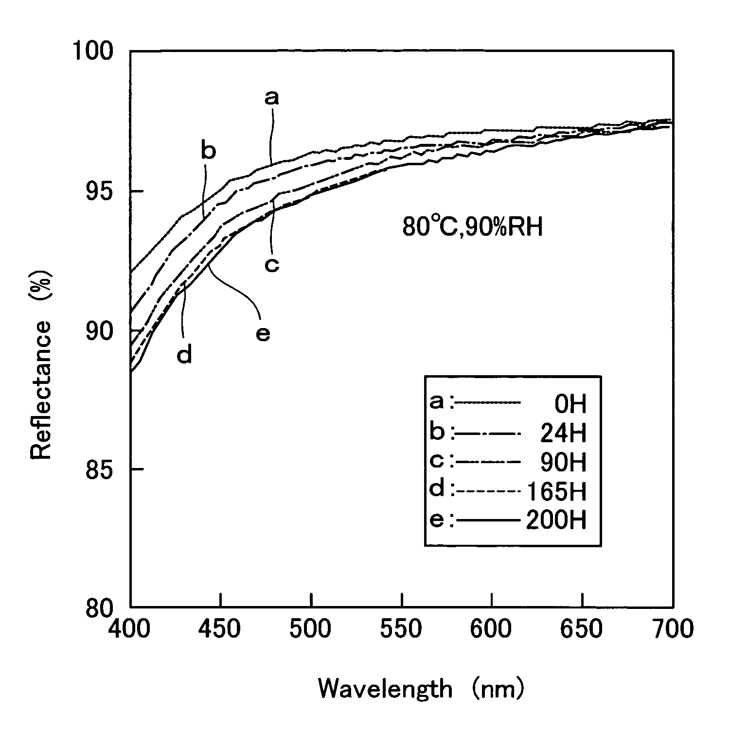
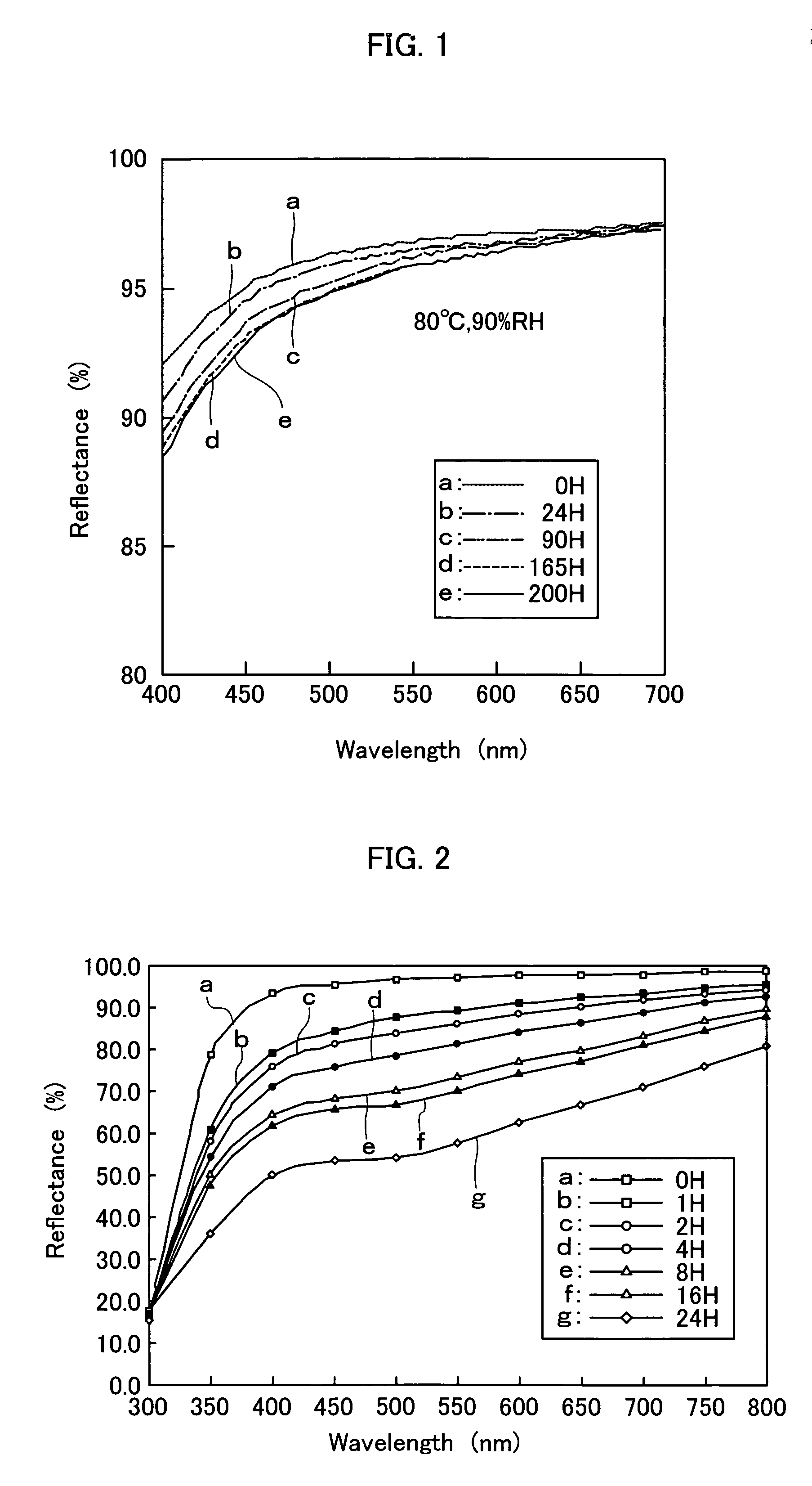
example 2

x Capping Layer>

[0073] As in the case of Example 1, an Ag-alloy target which comprised Ag as a principal component, 0.55 at % (1.0% by mass) of Au and 0.27 at % (0.3% by mass) of Sn was set, as the target 1b, on the cathode 1a arranged within the first sputtering chamber 1, while an Si target was set on the cathode 3a arranged within the sputtering chamber 3 as the target 3b.

[0074] An Ag-alloy film was formed on a glass substrate by repeating the same procedures used in Example 1 except for using the foregoing Ag-alloy target in a thickness of 150 nm and then the substrate was transferred to the second sputtering chamber 2. Thereafter, to the third sputtering chamber, there were introduced 60 SCCM of Ar gas and 40 SCCM of N2 gas, the pressure during sputtering film-formation was set at a level of 0.4 Pa and a DC power of 2000 W (a power density of 3.88 W / cm2) was applied to the Si target. Then the gate valve 6 positioned between the second sputtering chamber 2 and the third sputter...
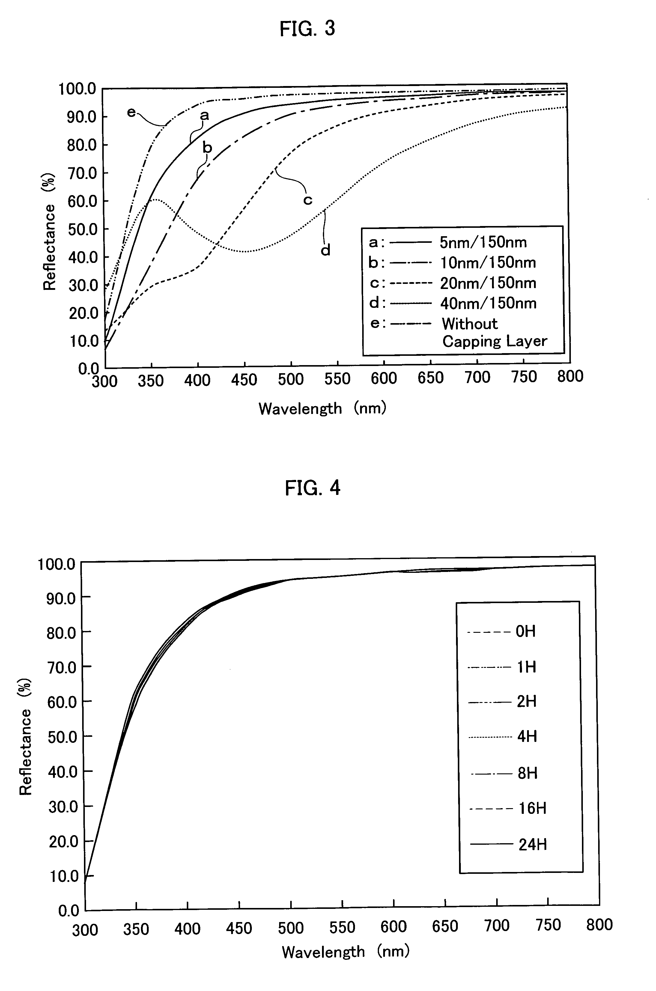
example 3

x Capping Layer>

[0077] An Ag-alloy target which comprised Ag as a principal component, 0.55 at % (1.0% by mass) of Au and 0.27 at % (0.3% by mass) of Sn was set, as the target 1b, on the cathode 1a arranged within the first sputtering chamber 1, while an Si target was set on the cathode 3a arranged within the sputtering chamber 3 as the target 3b.

[0078] An Ag-alloy film was formed on a glass substrate by repeating the same procedures used in Example 2 except for using the foregoing Ag-alloy target in a thickness of 150 nm and then the substrate was transferred to the second sputtering chamber 2. Thereafter, to the third sputtering chamber, there were introduced 70 SCCM of Ar gas and 30 SCCM of O2 gas, the pressure during sputtering film-formation was set at a level of 0.4 Pa and a DC power of 2000 W was applied to the Si target. Then the gate valve 6 positioned between the second sputtering chamber 2 and the third sputtering chamber 3 was opened and the tray 8 supporting the substr...


PUM

PropertyMeasurementUnit
thicknessaaaaaaaaaa
thicknessaaaaaaaaaa
thicknessaaaaaaaaaa

Abstract

An Ag-based reflection film consists of a laminate film comprising an Ag or Ag-alloy film provided thereon with a quite thin capping layer. The Ag-based reflection film can be prepared by, for instance, forming, on a substrate, an Ag or Ag-alloy film according to the sputtering technique, while using a sputtering target, for instance, having a composition corresponding to that of the pure Ag film, and Ar gas as a sputtering gas, while adding an additional gas such as O2, only at the initial stage of the Ag or Ag-alloy film-forming step; and then forming a quite thin capping layer, on the Ag or Ag-alloy film, according to the sputtering technique, while using a sputtering target having a composition corresponding to that of the capping layer, and Ar gas as a sputtering gas, while if necessary adding an additional gas such as O2. The Ag-based reflection film can maintain a high reflectance without causing any deterioration thereof even under the severe conditions such as those for the hydrogen sulfide-exposure test because of the presence of a quite thin capping layer. The reflection film may be applied to, for instance, those used for display devices and optics-relating ones.

Description

BACKGROUND OF THE INVENTION [0001] 1. Field of the Invention [0002] The present invention relates to an Ag-based reflection film and a method for the preparation of the same and more particularly to an Ag-based reflection film comprising an Ag or Ag-alloy thin film and a capping layer as well as a method for the preparation of the same. [0003] 2. Description of the Prior Art [0004] The Ag or Ag-alloy thin film has long attracted special interest as a reflection film used in the display device. However, it has been known that this Ag or Ag-alloy thin film suffers from a problem of low corrosion resistance. More specifically, the Ag or Ag-alloy thin film undergoes discoloration due to the reaction with sulfur- and / or chlorine-containing components present in the air or the surrounding atmosphere, the reflectance thereof is in turn reduced and the thin film is likewise inferior in the ability to adhere to a substrate or the adhesive properties. Accordingly, an upper protective film and...

Claims


Application Information

Patent Timeline
Patent Type & Authority Applications(United States)
IPC IPC(8): B32B15/04B32B9/00B32B19/00C23C14/00
CPCC03C17/36C03C17/3605C03C17/3626C23C14/185C03C17/3647C23C14/024C03C17/3644C23C28/3455
Inventor UKISHIMA, SADAYUKIISHIBASHI, SATORUSAITOU, SHIGERUKIM, POONG
Owner ULVAC INC
Why Eureka
Try Eureka